
Designing CNC Milled Parts: Fillets, Wall Thickness, and Too...
Designing CNC milled parts is about more than geometry in CAD. This guide explains how internal fillets, minimum wall th...
Designing CNC milled parts is about more than geometry in CAD. This guide explains how internal fillets, minimum wall th...
Learn how to design CNC‑ready parts with realistic tolerances, tool‑friendly features, and fewer setups. This guide expl...
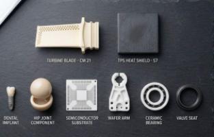
Navigate custom parts manufacturing with this technical guide covering CNC machining, urethane casting, sheet metal, and...
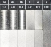
Master surface roughness with our complete guide. Understand Ra and Rz values, decode symbols, learn measurement methods...

Plastic fabrication is the process of transforming raw plastic materials into finished parts and products using methods...