About Laser Cutting
Laser Cutting Services
CO₂ Laser Cutting
Online Quote
For plastics like acrylic, CO₂ laser cutting with 10.6 μm infrared beam, creates exceptionally smooth, sealed edges in materials up to 20 mm thick-perfect for prototypes, consumer products and custom signage. With tolerances held to ±0.15 mm with minimal thermal impact.
Every single CO₂ laser-cut component from our certified manufacturing network undergoes rigorous in-house inspection. We verify dimensional accuracy and edge quality, so you receive parts that meet the highest standards-without delays, defects or surprises.
Fiber Laser Cutting
Online Quote
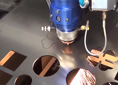
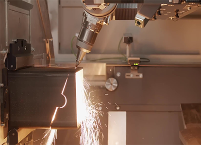
For projects that require precision and efficiency in metal cutting: Utilizing advanced solid-state technology that generates a highly concentrated 1.06 μm wavelength beam, our fiber lasers provide exceptional cutting speeds-up with remarkable accuracy making ideal for cutting a wide range of metals, including reflective materials like aluminum, copper and brass, as well as various grades of steel up to 30 mm thick.
Achieve tight tolerances of ±0.05 mm and repeatability, for the most complex features in enclosures, brackets and mechanical components. Every part produced in our manufacturing network undergoes rigorous in-house inspection.
Nd:YAG Laser Cutting
Online Quote
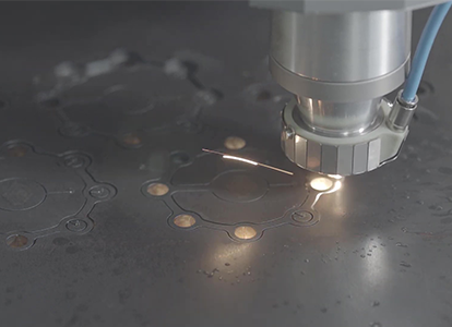
For highest level of precision in cutting advanced alloys and sensitive materials, our Nd:YAG laser cutting service delivers unmatched capabilities. Utilizing neodymium-doped yttrium aluminum garnet technology that generates high-peak-power pulses at 1.064 μm, processes thick alloys (including titanium and Inconel® up to 40 mm) while micromachining for critical medical device and aerospace components. The pulsed operation of Nd:YAG lasers minimizes heat input to preserve material properties.
Every Nd:YAG-processed component undergoes our rigorous in-house QA/QC protocol, including comprehensive thermal defect analysis.
Upload your CAD file to get an online CNC laser cutting quote for 2D sheet metal or 3D tube parts.
Laser Cutting Technical Capabilities
| Parameter | Our Specification |
|---|---|
| Maximum Part Size | 4000 × 2000 mm (157″ × 78″) |
| Minimum Part Size | 0.5 × 0.5 mm (micro-features) |
| Distance Dimensions | ±0.05 mm (engineer-assisted) |
| Max Material Thickness |
• Metals: 30 mm (steel), 25 mm (Al) • Plastics: 100 mm (acrylic) • Woods: 50 mm |
| Kerf (Slit Width) | 0.01-0.3 mm (laser-dependent) |
| Edge Condition | Ra 1.6-3.2 μm |
| Laser Sources | Fiber (1.06 μm), CO₂ (10.6 μm), Nd:YAG (1.064 μm) |
| Repeatability | ±0.02 mm |
| Positioning Accuracy | ±0.05 mm |
| Inspection & QA |
In-house CMM, material certification (MTRs), edge quality analysis, thermal defect screening |
| Lead Time |
Prototypes: 3 days Production: 5-7 days |
Laser Cutting Tolerance Standards
| Tolerance Type | Material Thickness | Standard Tolerance | Achievable Tolerance | Critical Applications |
|---|---|---|---|---|
| Dimensional Accuracy | 0.5-3 mm | ±0.10 mm | ±0.05 mm | Medical implants |
| 3-10 mm | ±0.15 mm | ±0.08 mm | Aerospace brackets | |
| 10-25 mm | ±0.20 mm | ±0.12 mm | Hydraulic valves | |
| Hole Diameter | <5 mm material | ±0.08 mm | ±0.04 mm | Sensor mounts |
| 5-15 mm material | ±0.12 mm | ±0.06 mm | Fluid ports | |
| >15 mm material | ±0.18 mm | ±0.10 mm | Structural fasteners | |
| Positional Accuracy | All thicknesses | ±0.05 mm | ±0.02 mm | PCB fixtures |
| Edge Perpendicularity | ≤10 mm | ±0.5° | ±0.2° | Sealing surfaces |
| >10 mm | ±1.0° | ±0.5° | Press-fit assemblies | |
| Surface Roughness (Ra) | Metals | 3.2-6.3 μm | 1.6-3.2 μm | Bearing seats |
| Plastics | 1.6-3.2 μm | 0.8-1.6 μm | Optical enclosures | |
| Kerf Consistency | Fine features | ±0.03 mm | ±0.015 mm | Microfluidics |
Laser Cutting Design Guidelines
| Design Aspect | Guideline | Technical Specification | Tip |
|---|---|---|---|
| File Preparation | Use vector files with closed shapes | DXF (2D), STEP/STP (3D), convert text to outlines | Remove overlaps/dimensions; verify 1:1 scale |
| Material & Thickness | Match detail size to thickness | Min. feature ≥ 50% thickness Max: 30 mm (steel), 25mm (Al), 100mm (acrylic) |
Avoid small holes in thick sheets; use standard sizes |
| Geometric Constraints | Account for kerf in joints | Kerf: 0.1-0.3 mm Inner: +½ kerf Outer: -½ kerf |
Adjust interlocking parts accordingly |
| Holes & Cutouts | Ensure hole size matches thickness | Min. hole: 1 mm (0.5-3 mm) 4mm (15-25 mm) ≥1× thickness from edge |
Avoid holes in side walls |
| Distances & Spacing | Keep adequate space between cuts | ≥2× thickness between cuts ≥0.5× for acrylics |
Use nesting software; avoid overheating |
| Corners & Edges | Avoid sharp corners; add fillets | Fillets: 0.3mm (≤3 mm), 0.1× thickness (>3 mm) | Add holes at slot corners; use edge-breaking |
| Assembly Features | Design with kerf compensation | Tab = thickness Slot = thickness + kerf |
Add nodes; chamfer tab ends |
| Tolerances & QA | Follow ISO 9013; specify finishing | ±0.2 mm (≤3 mm sheets) ±0.45 mm (20-25 mm sheets) |
Expect discoloration near fine features |
Notes:
Kerf Compensation: Essential for press-fit assemblies (e.g., puzzle joints, enclosures). Neglecting it causes loose/tight fits.Material Restrictions: Avoid PVC, fiberglass or chlorinated materials (emit toxic fumes).
Engraving Limitations: Only functional engravings allowed; must not cross outer contours and require ≥0.2mm depth in STEP files.
Thermal Management: Small geometries (e.g., narrow webs) may discolor due to heat buildup-redesign for heat dissipation.
Advantages of Laser Cutting
Precision and Repeatable Accuracy
Laser cutting achieves tolerances within ±0.10 mm, enabling complex geometries, sharp corners and micro-features down to 0.5 mm. The non-contact process eliminates tool wear, ensuring consistent results across production runs-critical for aerospace, electronics and medical components requiring strict dimensional compliance.
Material Versatility without Tooling Constraints
The technology processes diverse materials-including metals (steel, aluminum, titanium), engineering plastics (acrylic, polycarbonate), woods and composites-without mechanical tool changes. Fiber lasers (1.06 μm wavelength) effectively cut reflective metals like copper, while CO₂ lasers (10.6 μm) optimize edge quality in organics.
Reduced Thermal Distortion and Contamination
Localized heat input minimizes warping in thin sections. As a non-contact method, it prevents material contamination from cutting tools-essential for cleanroom applications. Fume extraction systems manage sublimation byproducts in plastics.
Operational Efficiency and Speed
Digital workflows allow rapid job switching, eliminating fixture setups. Cutting speeds reach 10-40 m/min (material-dependent), enabling same-day prototyping. Integrated nesting software optimizes material yield, reducing waste by 15-30% versus mechanical methods.
Minimal Post-Processing Requirements
Laser-cut edges exhibit surface roughness (Ra) of 1.6-6.3 μm, often eliminating secondary deburring. Kerf widths as narrow as 0.1 mm preserve detail in dense patterns.
Scalability from Prototype to Production
The process supports single-part validation to high-volume batches (10,000+ units) with identical parameters, bridging development and manufacturing phases seamlessly.
Laser Cutting Applications
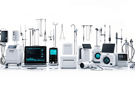
Medical & Dental Components
Precision-cut surgical tools, implant templates (±0.05 mm tolerances) and MRI-compatible stainless steel (316L) or titanium enclosures.
Micro-cutting (features ≤0.3 mm) enables vascular stents and orthodontic brackets with burr-free edges (Ra ≤1.6 µm), ensuring biocompatibility and sterilization compliance.
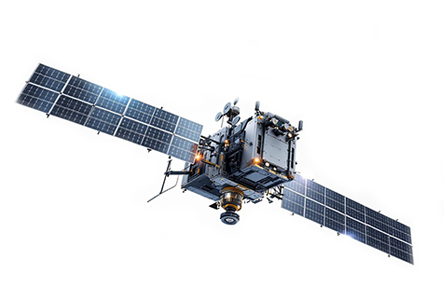
Aerospace & Defense Systems
Structural airframe components (aluminum 7075,
≤20 mm thickness), turbine engine heat shields (Inconel®) and satellite brackets requiring
AS9100-compliant traceability. Fiber lasers cut complex geometries in refractory alloys without inducing stress concentrations critical under G-forces.
Electronics & Microtechnology
EMI/RF-shielding enclosures (beryllium copper), flexible circuit boards (polyimide) and semiconductor wafer scribing.
Non-contact processing prevents electrostatic discharge (ESD) damage, while UV lasers achieve kerfs <20 µm for high-density interconnects.
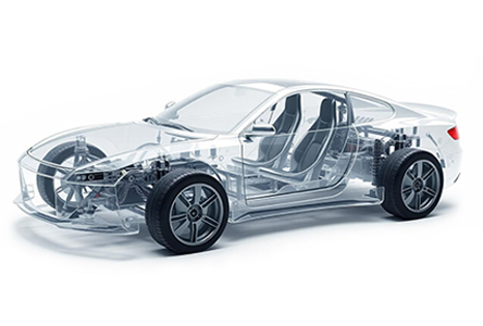
Automotive & EV Manufacturing
Battery tray components (aluminum 6061-T6, ≤15 mm), transmission shims (spring steel) and lightweight interior panels (carbon fiber composites).
Nesting optimization reduces material waste by 18-22% versus stamping for low-volume EV prototyping.
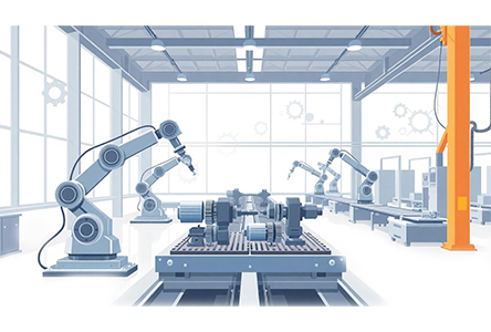
Industrial Machinery & Tooling
Hydraulic valve plates (hardened tool steel, HRC 45±2) with precision fluid ports (±0.08 mm).
Laser-cut tooling blanks enable faster die fabrication versus wire EDM, with lead times under 72 hours for replacement parts.
Architecture & Consumer Goods
Decorative metal screens (corten steel, 8 mm), acrylic signage with polished edges and wooden inlays for furniture.
CO₂ lasers process non-metals up to 100 mm thickness while maintaining ±0.2 mm positional accuracy for large-format art installations.
Clarwe's Quality & Certifications Guarantee
All parts are validated in-house: Clarwe's Guarantee of Zero-Defect Parts
Every component is sourced from our vetted ISO/AS-certified manufacturing partners, then 100% physically inspected at our facility before shipment. Unlike others, we enforce a 3-stage custody protocol:
| Material Compliance: | We order and validate material certifications (RoHS, REACH, mill test reports) on your behalf. |
| In-House Verification: |
Dimensional accuracy checks via CMM, VMM, 2D height gauges and precision tools. Critical feature validation against your drawings (hole positions, thread fits, flatness). Visual inspection for surface defects, burrs and cosmetic flaws. |
| Final Certification: | Full documentation including material certs, CoCs and inspection logs. |
| We guarantee: | ±0.020 mm tolerances on all
shipped parts (validated in-house). Zero paperwork gaps – we manage all supplier certifications. 100% physical custody – no direct supplier shipments delivering zero-defect compliance from prototype to 100,000+ part production runs. |
Why Choose Clarwe Laser Cutting Services?
Our platform integrates a vetted global network of ISO 9001:2015-certified manufacturing partners with centralized in-house QA/QC, ensuring consistent precision (±0.1 mm standard, ±0.05 mm achievable) across all outputs-unlike decentralized models where quality varies by supplier. Every component undergoes rigorous in-house dimensional validation (CMM), material certification and thermal defect screening, guaranteeing compliance for medical, aerospace, or automotive applications. This unified approach enables scalable production (1-10,000+ units) with 3-7 day lead times while eliminating supply-chain quality risks.
Technical specialization is enforced through laser technology matching-assigning fiber, CO₂ or Nd:YAG systems based on your material, thickness (up to 30 mm metals/100 mm plastics) and tolerance requirements-coupled with full inspection reports for traceability. The result: risk-mitigated manufacturing from prototype to batch production under a single quality standard.
Clarwe's Platform Advantage
Our integrated dashboard delivers end-to-end project command-streamlining workflows while ensuring transparency at every stage. Experience seamless coordination from initial request to final delivery, all within a single secure interface.
Submit & Configure
| RFQ Initiation |
Upload CAD files (STEP, IGES, SLDPRT) and drawings Specify requirements: materials, tolerances, finishes, inspection protocols Request custom documentation: material certs, CMM reports, customs forms |
| Real-Time Quoting |
Receive online DFM analysis with cost drivers flagged Adjust configurations (e.g., material substitutions) to optimize pricing |
Order Execution & Oversight
| Document Management |
Submit customs declarations, commercial invoices and HS codes Upload purchase orders or approve terms for payment Access digital invoices with tax/line-item breakdowns |
| Production Intelligence |
Track progress and updates View Shop floor photos/videos Access Inspection reports, quality documents and Material certifications Monitor shipping status with carrier integrations |
Proactive Collaboration & Support
| Engineer Engagement |
Send technical queries and status enquiries to our engineers via encrypted chat Receive resolution timelines for technical queries |
| Quality Assurance Hub |
Access pre-shipment documentation: First-article inspection reports, dimensional reports and quality
documents Approve/reject deliverables via annotated media |
| Post-Delivery Excellence |
Initiate reorders with one-click cloning Log support tickets for non-conformances Archive project history (drawings, certs, comms) for audits |
Industries specialized
Aerospace
Automotive
Consumer Products
Medical
Ready to get started?
Frequently Asked Questions about CNC Laser Cutting
Standard dimensional tolerances are ±0.10 mm, with ±0.05 mm achievable for critical features through engineer-assisted optimization. Repeatability is maintained at ±0.02 mm across production runs via in-house CMM validation.
Metals: Steel (≤30 mm), aluminum (≤25 mm), copper/brass (≤15 mm).
Plastics: Acrylic/Polycarbonate (≤100 mm).
Woods/Composites: ≤50 mm.
Exotics: Titanium (≤20 mm), Inconel® (≤15 mm).
Yes. Fiber lasers (1.06 μm wavelength) with nitrogen assist gas prevent reflection issues, enabling clean cuts in copper/brass up to 15 mm.
We laser cut a wide range of materials, including metals (mild steel up to 30 mm, stainless steel up to 25 mm, aluminum up to 25 mm, copper and brass up to 15 mm), plastics (acrylic and polycarbonate up to 100 mm) and composites and woods (up to 50 mm). Reflective or highly conductive materials like copper require specialized fiber laser systems to manage reflectivity and heat dissipation.
We accept vector-based formats ideal for 2D cutting paths, including DXF, DWG, AI, PDF and STEP. For 3D files, we can process STEP, IGES and SLDPRT. Our automated system includes DXF repair functionality to correct common file issues like open contours or overlapping lines, ensuring manufacturability before quoting.
We minimize HAZ through parameter optimization (adjusting pulse frequency, power and cutting speed) and assist gas selection (nitrogen for non-oxidizing cuts, oxygen for faster speeds). For delicate materials or fine features, we utilize specialized techniques to limit HAZ to ≤0.25 mm. Design for Manufacturability (DFM) feedback is provided to address thermal risks before production.
Prototypes are typically shipped within 3 business days after file approval. Production runs (1-10,000+ units) are completed in 5-7 business days. These accelerated timelines are possible due to our networked manufacturing model and the elimination of quality inspection handoffs through centralized QA.
Yes, we offer a comprehensive suite of finishing services, including mechanical deburring, bead blasting, powder coating, anodizing (Type II & III) and silk screening. These can be seamlessly integrated into your order, providing a single-source solution for finished parts.
Our services are tailored to meet the stringent requirements of medical (ISO 13485), aerospace (AS9100), automotive, electronics and industrial machinery sectors. We maintain full material traceability and provide the necessary documentation for regulatory compliance in these industries.
The minimum feature size is generally 1:1 with the material thickness (e.g., a 1 mm wide feature in 1 mm thick material). For standard materials, we can achieve features as small as 0.5 mm. For true micromachining applications requiring features smaller than 0.3 mm, we recommend discussing your project with our engineering team for a specialized solution.
Our partner network is rigorously vetted and certified to ISO 9001:2015. Crucially, we do not outsource quality control. All parts are shipped to our facility for standardized, in-house inspection against the same precise criteria, regardless of the manufacturing origin. This unique model provides the scalability of a network with the consistency of a single supplier.