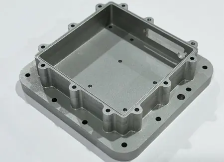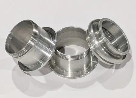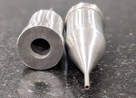
Transition smoothly from rapid functional engineering models to high-volume blanket production cycles.
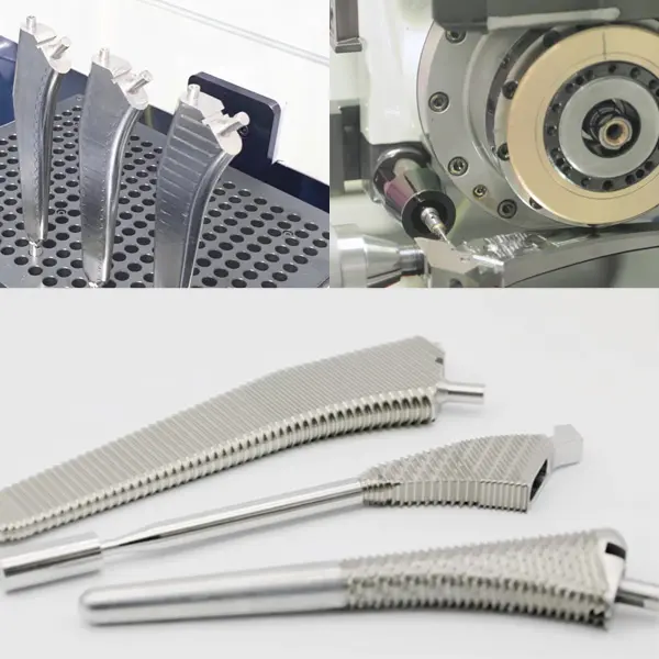
Distributed global manufacturing capacity managed through an absolute, centralized quality checkpoint. Clarwe takes full ownership of quality control.
Every manufacturing lot generated across our elastic partner network is routed directly to Clarwe’s corporate quality control labs before final dispatch.
We physically verify critical dimensions, bore true positions, and surface profile deviations using Zeiss CMMs, optical vision systems, and calibrated thread plug gauges.
Your components arrive at your dock alongside full material traceability records, Mill Test Certificates (MTCs), RoHS/REACH compliance logs, and aviation-grade AS9102 First Article Inspection Reports (FAIR) upon request.
Balance functional requirements with cost-efficiency by referencing our standard and achievable tolerance matrices below.
| Process | Feature | General Tolerance | Tight / Achievable Tolerance |
|---|---|---|---|
| Milling | Linear Dimensions | ±0.125 mm (±0.005") | ±0.025 mm (±0.001") |
| Hole Position (Ø <25 mm) | ±0.100 mm | ±0.012 mm | |
| Bore Diameter (H7 fit) | ±0.050 mm | ±0.007 mm | |
| Flatness (100×100 mm) | 0.100 mm | 0.015 mm | |
| Surface Finish (Ra) | 3.2 μm (125 μin) | 0.4 μm (16 μin) | |
| Turning | Diameter (Ø <50 mm) | ±0.075 mm | ±0.015 mm |
| Length | ±0.100 mm | ±0.020 mm | |
| Concentricity | 0.050 mm | 0.010 mm | |
| Thread Pitch Compatibility | Standard Class 6g/6H | Precision Class 4g/4H | |
| Surface Finish (Ra) | 1.6 μm (63 μin) | 0.2 μm (8 μin) | |
| Wire EDM | Linear Dimensions | ±0.020 mm | ±0.004 mm |
| Corner Radius | R0.15 mm | R0.05 mm | |
| Surface Finish (Ra) | 1.6 μm (63 μin) | 0.8 μm (32 μin) | |
| Sinker EDM | Cavity Depth | ±0.030 mm | ±0.010 mm |
| Blind Keyway Width | ±0.025 mm | ±0.008 mm | |
| Surface Finish (Ra) | 3.2 μm (125 μin) | 0.8 μm (32 μin) |
This reference details critical dimensional limits across hole positions, surface flatness and geometric profiles to balance precision with manufacturability.
| Feature | CNC Milling | CNC Turning | EDM (Wire/Sinker) |
|---|---|---|---|
| Wall Thickness | 1.0 mm (metals) 1.5 mm (plastics) |
0.8 mm (metals) 1.2 mm (plastics) |
0.3 mm (hardened steel) >0.5 mm (carbide) |
| Hole Depth | ≤6x diameter Min. Ø: 0.5 mm |
≤5x diameter Min. Ø: 0.3 mm |
Through-cuts only (Wire) ≤20x Ø (Sinker) |
| Internal Corners | ≥R0.5 mm Radii <R0.5 mm may require EDM |
≥R0.3 mm Min: R0.1 mm |
Wire: R0.05 mm Sinker: R0.1 mm |
| Thread Depth Limit | Blind Holes: ≤2x ∅ Through Holes: ≤3x ∅ |
Blind Holes: ≤2x ∅ Through Holes: ≤3x ∅ |
Threaded features require specialized electrodes or tapping operations |
| Tolerances (Standard) | ±0.125 mm | ±0.075 mm | Wire: ±0.020 mm Sinker: ±0.030 mm |
| Tolerances (Tight) | ±0.020 mm (Premium applied) | ±0.015 mm (Premium applied) | Wire: ±0.004 mm Sinker: ±0.010 mm |
| Text Engraving | Min Width: 0.4 mm Depth: ≤0.5 mm |
Min Width: 0.4 mm Depth: ≤0.3 mm |
Not recommended (Spikes electrode wear) |
| Thread Limits | Minimum: M2 (Cut) M1.6 (Formed) |
Minimum: M1 (External) M1.2 (Internal) |
Threaded features require specialized electrodes or tapping operations |
| Undercuts | Avoid unless using 5-Axis milling Min Width: 3.0 mm |
T-Slots / Grooves allowed via live tooling Min Width: 1.5 mm |
Standard capability in blind cavities Min Width: 0.1 mm |
| Surface Finish (Ra) | As-Machined: 3.2 μm Polished: down to 0.4 μm |
As-Turned: 1.6 μm Polished: down to 0.2 μm |
Wire EDM: 0.8 μm Sinker EDM: 1.6 μm |
| Critical Engineering Tips | • Add 1° to 2° draft angles for deep pockets. • Avoid internal cross-holes <∅1 mm. |
• Include a 0.2 mm×45° chamfer on sharp edges. • Limit Max L/D Aspect Ratio to 10:1. |
• Wire: Avoid taper cuts >15°. • Sinker: Allow a minimum of 0.3 mm spark gap clearance for electrodes. |
Upload your CAD to receive a comprehensive DFM (Design for Manufacturing) analysis, material validation, and competitive volume pricing.
| Metal | Alloys |
| Aluminum | Al 2014 (T6), Al 2017A, Al 2024-T351, Al 5052 (H32), Al 5083 (H32, H111), Al 6061 (T6, T651), Al 6063 (T5, T6), Al 6082 (T6, T651), Al 7050, Al 7075 (T6, T651, T7351) |
|---|---|
|
Copper |
Copper C101, Copper C110 |
| Brass | Brass C360 |
| Bronze | 932 Bearing Bronze, 954 Bearing Bronze, 544 Bearing Bronze |
| Tool Steel | A2 Tool Steel, D2 Tool Steel, A3 Tool Steel, O1 Tool Steel, S7 Tool Steel, H13 Tool Steel |
| Stainless Steel | SS 304, SS 316, SS 303, SS 416, SS 2205 (Duplex), SS 420, SS 440C, SS 430, SS 301 |
| Alloy Steel |
Alloy Steel 4140, Alloy Steel 4340, Alloy Steel 1215 |
| Mild Steel | Mild Steel 1018, Mild Steel 1045, Mild Steel A36 |
| Titanium | Titanium Grade 1, Titanium Grade 2, Titanium Grade 5 (Ti-6Al-4V) |
| Plastic | Grades |
|---|---|
| ABS | Machine grade, Flame retardant UL94 V-0 |
| Acrylic | PMMA, Clear, Impact modified |
| Delrin | Delrin (POM-C), Delrin (POM-H) |
| HDPE | High-density polyethylene, FDA compliant grade |
| Nylon | Nylon 6/6, Nylon 6 (30% Glass Filled) |
| Polycarbonate | Lexan, Machine grade, 20% glass-filled |
Optimize part longevity, corrosion resistance, and cosmetic value with print-specified surface treatments.
| Finish | Technical Specification | Best Structural Use Case |
| As-Machined | Ra 3.2 μm (125 μin) down to Ra 0.8 μm | Internal structural frames, bracketry, and non-cosmetic prototypes. |
| Anodizing Type II | MIL-A-8625 Type II (Sulfuric acid anodizing, Clear/Colored) | Corrosion resistance and cosmetic surface coloring for aluminum enclosures. |
| Chem Film / Alodine | (MIL-DTL-5541) | Electrical conductivity retention and corrosion resistance for aerospace aluminum components. |
| Bead Blasting | Class A uniform matte finish (various glass bead grits) | Removing directional tool marks; excellent prep coat for anodizing. |
| Hardcoat Type III | MIL-A-8625 Type III (Wear-resistant oxide barrier, up to 50 μm) | Aerospace gears, sliding mechanisms, high-wear industrial components. |
| Passivation | ASTM A967 / AMS 2700 (Citric or Nitric Acid treatments) | Eliminating free iron from stainless steel surfaces (SS304/SS316) for medical and marine applications. |
For multi-axis CNC milling, our maximum physical bed travel handles components up to 2000 mm x 1200 mm x 800 mm. For high-speed CNC turning, we can process a maximum diameter of 450 mm and a maximum part length of 800 mm.
Yes. While standard geometries can be processed from step files using our general tolerance matrix (±0.125 mm), custom PDF technical drawings are required to execute tight, high-precision tolerances down to ±0.005 mm, custom geometric dimensioning and tolerancing (GD&T), or specific surface finishing requirements.
All 3D models and production prints uploaded to our secure platform are fully encrypted both in transit and at rest. File access is locked down strictly to assigned project engineers, and your intellectual property is automatically protected under a binding Mutual Non-Disclosure Agreement (NDA).
Because we anchor raw material costs securely through centralized inventory channels, all manual, engineer-verified line-item quotes remain completely locked and valid for exactly 30 days from issuance.