

Ceramic CNC machining is the shaping of technical ceramics on CNC equipment, and the single most useful thing to know before you specify a part is this: once a ceramic is fired, almost none of the work is milling. It is grinding, with diamond abrasive, at low removal rates. That one fact drives the tolerances you can call out, the features you can afford, and the price you get back.
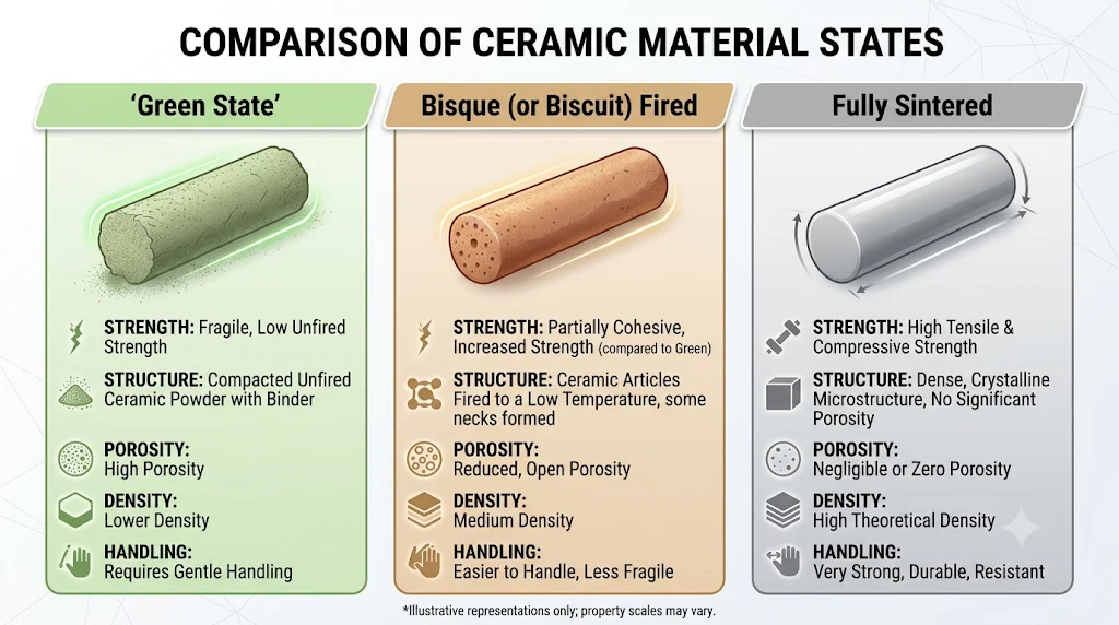
There are three points in a ceramic's life where material can be removed: before firing (green), after a partial pre-sinter (bisque), and after full sintering (hard). Green and bisque machining are fast and cheap but every dimension moves during firing. Hard machining holds micron-level tolerances but costs several times as much per feature. A well designed ceramic part uses both: rough the bulk before firing, grind only the surfaces that have to be right.
This guide covers how to choose between those states, what each common ceramic does under the wheel, what tolerances and finishes are realistic, and the design rules that keep a ceramic part quotable.
Why Sintered Ceramics Are Ground, Not Milled
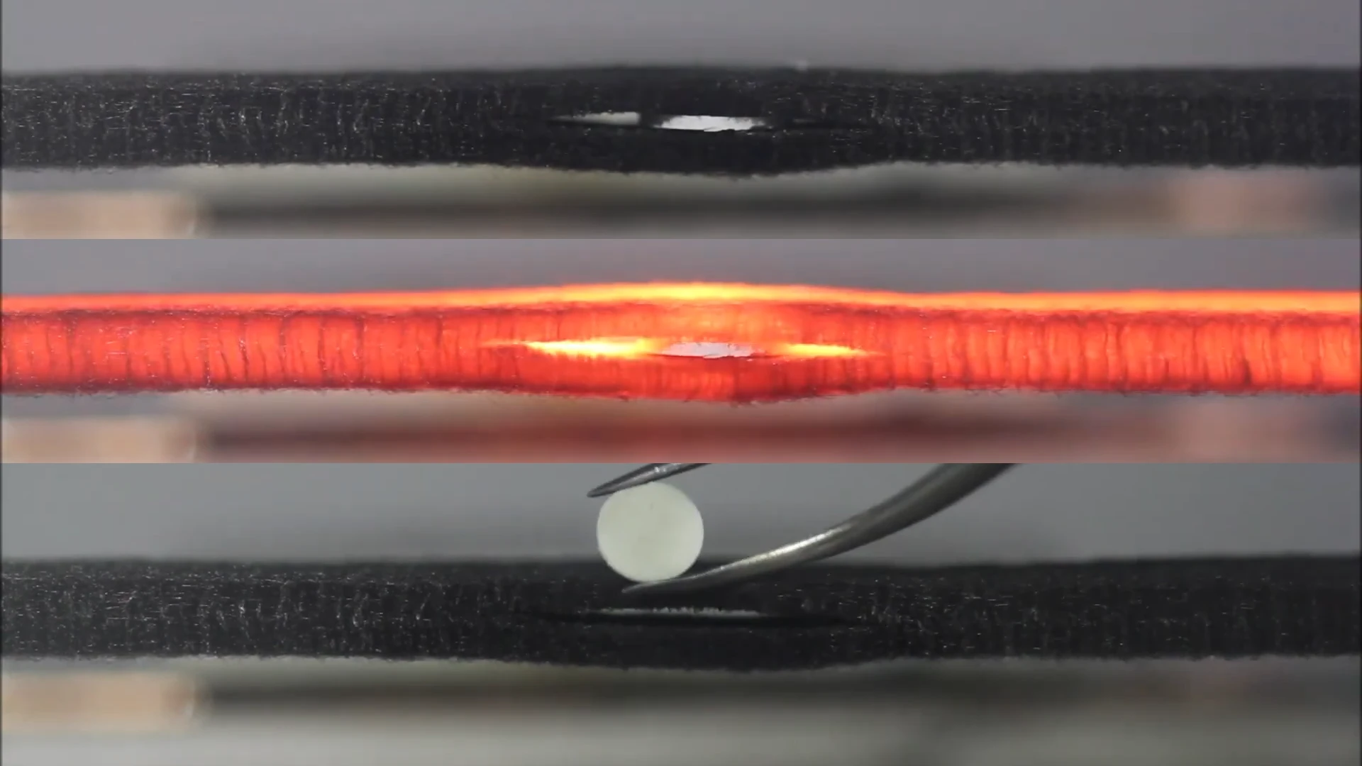
Technical ceramics fail by fracture, not by plastic flow. A steel chip forms because the metal shears ahead of the cutting edge. A sintered alumina chip forms because a network of microcracks runs ahead of the tool and pieces break away. Push harder and the crack goes where it wants, which is into the part.
Hardness is the second problem
Sintered silicon carbide sits at roughly 2,400 to 2,600 HV. Carbide tooling is around 1,600 to 1,800 HV, so a carbide end mill cannot cut it at all. Only diamond, and in narrow cases cubic boron nitride, is harder than the workpiece. In practice that means resin or metal bonded diamond wheels, diamond plated end mills for slots and pockets, and diamond core drills for holes.
What this changes on your drawing
Grinding is a surface-by-surface process, not a shape-generating one. Each ground face, bore, or diameter is a separate setup with its own wheel, dress cycle, and inspection step. A ceramic drawing that calls out a tight tolerance on twelve surfaces is not slightly more expensive than one that calls out three. It is a different part.
Green, Bisque, or Hard: Choosing the Machining State
Most cost decisions in a ceramic part are made here, before any tolerance is discussed.
Green machining
The part is a pressed or cast powder compact held together with binder. It cuts with conventional tool steel or carbide tooling on standard CNC equipment, dry, with vacuum extraction because coolant dissolves the binder. Material removal is fast and tool wear is minimal.
The catch is shrinkage. The part contracts during sintering, commonly around 15 to 20 percent linear depending on material, powder, compaction, and furnace loading. Every green dimension has to be scaled up:
green dimension = target fired dimension / (1 - validated linear shrinkage)
That shrinkage figure has to come from the supplier's validated data for that specific material and process, not from a published average. Shrinkage is also directional, and real parts bow and camber on top of the uniform scaling, so green machining alone will not hold a precision fit.
Bisque machining
The compact is pre-sintered to partial density, sometimes called the white body or biscuit stage. Binder is burned out, so the part handles without crumbling, but it is still soft enough for carbide tooling. Bisque machining trades some of green machining's speed for much better handling strength and dimensional predictability, and it is the usual choice for holes, cross drilling, and thin features that would break in the green state.
Hard machining after sintering
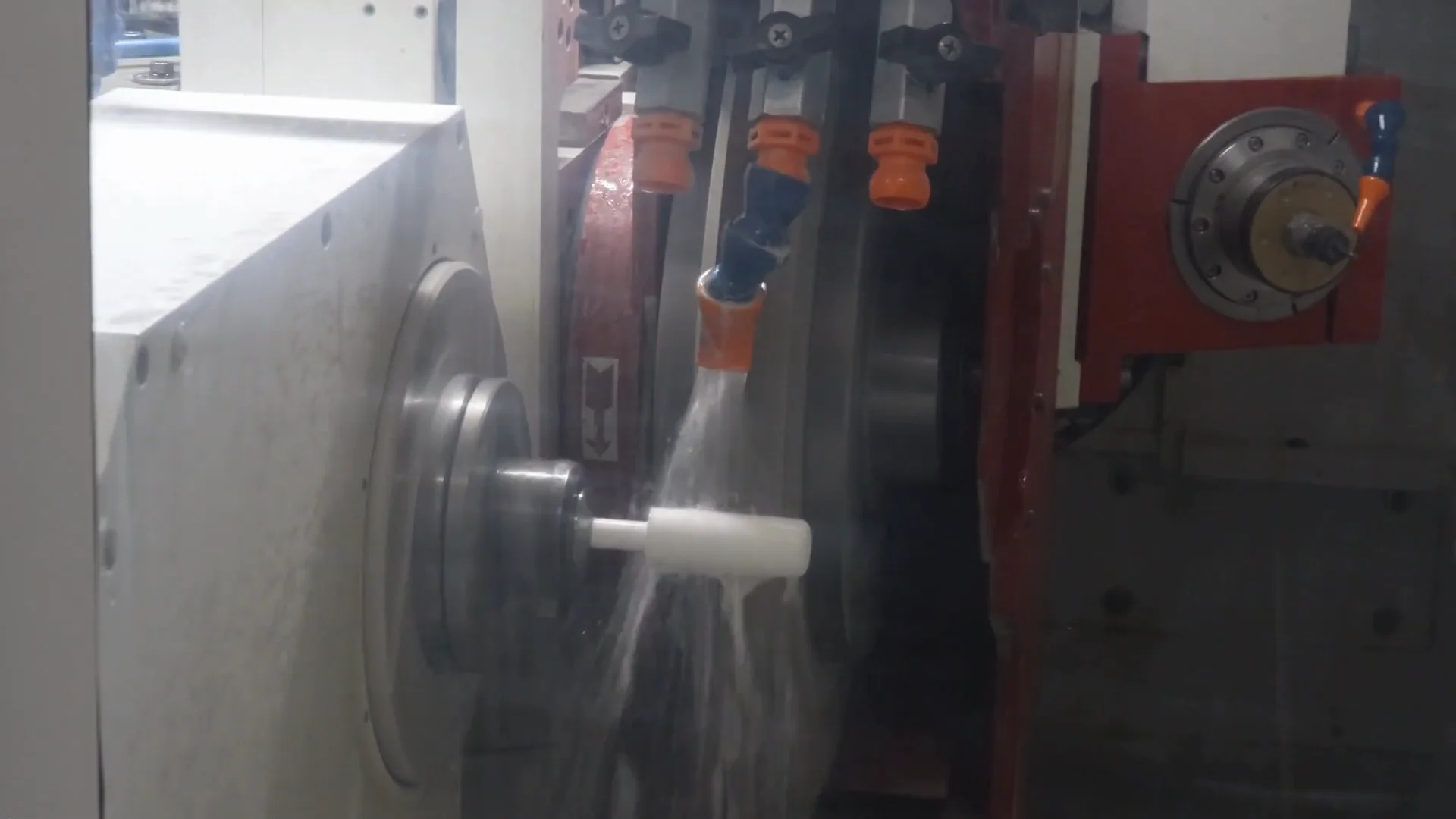
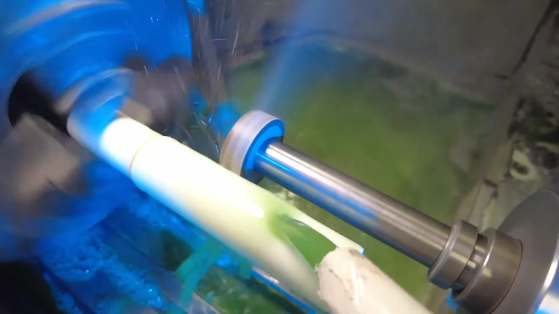
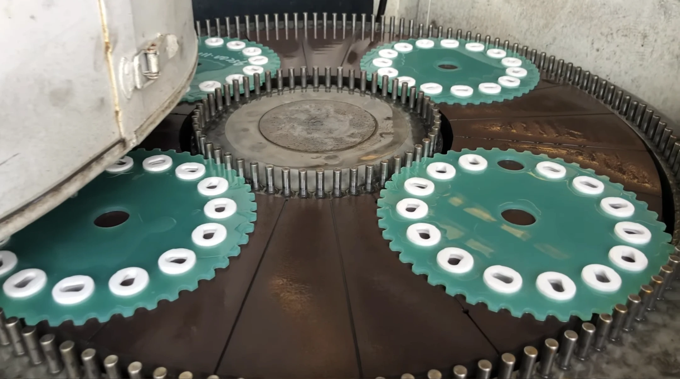
The part is at full density and full hardness. Everything from here is diamond grinding, lapping, or polishing. Typical parameters are a wheel surface speed around 20 to 45 m/s, depth of cut in the 2 to 20µm (0.00008 to 0.0008in) range, and continuous flood coolant to flush swarf and keep the grind zone temperature steady.
Coolant strategy is worth stating plainly because it is often described backwards: sintered ceramics are ground wet, with generous continuous flood. The thermal shock risk comes from interrupted or inconsistent coolant, not from the coolant itself. Green and bisque parts are the ones cut dry, because water attacks the binder.
How the three compare
| Green | Bisque | Hard (sintered) | |
|---|---|---|---|
| Tooling | Tool steel, carbide | Carbide | Diamond wheels and tools |
| Relative removal rate | Fastest | Fast | Slowest |
| Relative cost per feature | Lowest | Low | Highest |
| Dimensional certainty | Low, shrinkage dependent | Low, shrinkage dependent | High |
| Coolant | Dry, vacuum extraction | Dry or minimal | Continuous flood |
| Best for | Bulk removal, pockets, profiles | Holes, cross features, thin walls | Datums, fits, seal faces, finishes |
Which features to machine at which stage
Machine before firing anything that removes a lot of material, becomes unreachable later, or does not carry a tight tolerance: deep pockets, channels, grooves, reliefs, cross holes, rough bores, and cosmetic profiles.
Reserve diamond grinding for the features that define function: datum faces, locating diameters, precision bores, sealing surfaces, controlled thickness, flatness, parallelism, runout, and any surface with a roughness callout. If a feature does not appear in that list, it probably does not need to be ground, and saying so on the drawing is one of the fastest ways to reduce a ceramic quote.
Ceramic Materials and How They Machine
Property tables are easy to find. What matters for a machined part is how each material behaves under a diamond wheel and what it costs to hold a tolerance on it.
| Material | Vickers hardness (HV) | Fracture toughness (MPa·m½) | Thermal conductivity (W/m·K) | Behavior under the wheel |
|---|---|---|---|---|
| Alumina, 96 to 99.5% Al₂O₃ | ~1,440 at 99.5%, lower at lower purity | ~4 | 24 to 35 | The default. Green machines well, grinds predictably, widest supply base |
| Zirconia, 3Y-TZP | 1,300 to 1,350 | 9 to 10 | 2 to 3 | Toughest of the group, most forgiving on thin sections and edges. Low conductivity traps heat at the grind zone |
| Silicon nitride, sintered | 1,450 to 1,650 | 6 to 7.5 | 20 to 30 | Grinds well for its hardness, good thermal shock resistance, expensive stock |
| Silicon carbide, sintered | 2,400 to 2,600 | ~4 | 110 to 150 | Hardest common grade. Slowest to grind, heaviest wheel wear, highest finishing cost |
| Aluminum nitride | ~1,000 | ~3 | ~170 | Chosen for heat transfer. Low toughness, so edges and thin sections need care |
| Macor machinable glass ceramic | Knoop ~250 | Low, 94 MPa modulus of rupture | 1.5 | Cuts with carbide on a standard mill, no firing step, no shrinkage |
Choosing between alumina and zirconia
This is the decision most projects actually face. Alumina is harder, stiffer, far better at high temperature, a better electrical insulator at heat, and cheaper. Zirconia is roughly twice as tough, survives thin walls and sharp-ish features that would chip alumina, and is the usual choice for biocompatible parts.
Zirconia's weakness is heat. At 2 to 3 W/m·K it barely conducts, so grinding heat concentrates in a thin surface layer. Aggressive removal on Y-TZP can drive a surface phase transformation that roughens the finish and leaves residual stress, which is why finishing passes on zirconia are kept light and well flooded. Zirconia is also limited to roughly 800 to 1,000°C in service, against 1,750°C no-load for high purity alumina.
When thermal conductivity is the requirement
Aluminum nitride at around 170 W/m·K and silicon carbide at 110 to 150 W/m·K are the two options when a part has to insulate electrically and conduct heat at the same time. AlN also has a CTE near 4.5 x 10⁻⁶/K, close to silicon, which is why it dominates semiconductor and power electronics substrates. It is the least tough material in the table, so design in generous edge breaks and avoid unsupported thin sections.
When machinability matters more than hardness
Macor and machinable aluminum nitride grades cut with ordinary carbide tooling on ordinary CNC machines and need no firing afterward, so there is no shrinkage to compensate and no diamond grinding step. Corning's data for Macor cites dimensional capability to about ±0.013mm (±0.0005in) with ground surfaces below 0.5µm Ra and polished surfaces near 0.013µm Ra, at a continuous use temperature of 800°C. For fixtures, insulators, vacuum feedthroughs, and prototypes that need one or two pieces next week, it is usually the right answer even though it is far softer than a true technical ceramic.
Tolerances and Surface Finish You Can Actually Specify
The most misleading claim in this category is a blanket "0.001mm precision." Precision in ceramics is per feature, per process, and per cost.
As-fired tolerances
A part that is machined green or bisque and then fired, with no post-fire grinding, lands in a band commonly given as ±0.13mm (±0.005in) or ±1 percent of the feature dimension, whichever is larger. That is the number to design to for every surface you are not paying to grind. As-fired internal features also need draft: a common guideline is 2 degrees, or about 0.006mm per mm of length (0.006in per inch).
Ground tolerances
| Process | Typical dimensional tolerance | Typical surface finish (Ra) |
|---|---|---|
| As-fired, no post-machining | ±0.13mm (±0.005in) or ±1% of dimension | As-fired texture, grade dependent |
| Surface grinding, flat features | ±0.005mm (±0.0002in) | 0.2 to 0.4µm (8 to 16µin) |
| Cylindrical grinding, OD | ±0.003mm (±0.0001in) | 0.2 to 0.4µm (8 to 16µin) |
| Internal and bore grinding | ±0.005 to ±0.010mm (±0.0002 to ±0.0004in) | 0.2 to 0.4µm (8 to 16µin) |
| Lapping | Set by the flatness or form callout | 0.05 to 0.2µm (2 to 8µin) |
| Polishing | Set by the form callout | 0.025µm (1µin) and below |
Tighter than this is achievable in ultraprecision work. Ductile mode machining, where the undeformed chip thickness is held below a material specific critical value in the sub-micron range so the ceramic flows plastically instead of fracturing, produces optical surfaces directly off the machine. It requires ultraprecision spindles, sub-micron feed control, and long cycle times, so treat it as a specialist route for optics and semiconductor components rather than something to assume on a general quote.
How to specify finish sensibly
Call out roughness only on surfaces where it does work: sealing faces, sliding interfaces, optical surfaces, bonding surfaces, and anything a vacuum or plasma sees. A general Ra note applied to a whole ceramic part means every face gets ground, which is the single most common reason a ceramic quote comes back higher than expected. For background on interpreting roughness callouts, see the surface roughness chart.
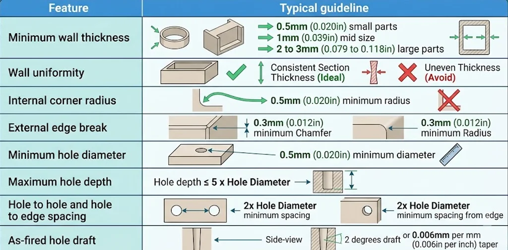
Design Rules for Machined Ceramic Parts
These are typical starting points across common technical ceramics. Confirm the exact limits for your grade and geometry with the supplier, because they shift with material, part size, and aspect ratio.
| Feature | Typical guideline | Reason |
|---|---|---|
| Minimum wall thickness | 0.5mm (0.020in) on small parts, 1mm (0.039in) mid size, 2 to 3mm (0.079 to 0.118in) on large structural parts | Thin sections crack during firing, handling, and grinding |
| Wall uniformity | Keep section thickness as consistent as the function allows | Uneven sections shrink unevenly and warp during firing |
| Internal corner radius | 0.5mm (0.020in) minimum | Sharp internal corners are stress risers and crack initiation sites |
| External edge break | 0.3mm (0.012in) chamfer or radius minimum | Unbroken edges chip in handling, fixturing, and shipping |
| Minimum hole diameter | 0.5mm (0.020in) | Diamond core drill and tool stiffness limits |
| Maximum hole depth | 5x the hole diameter | Tool deflection and swarf evacuation |
| Hole to hole and hole to edge spacing | 2x the hole diameter minimum | Keeps the crack path between features intact |
| As-fired hole draft | 2 degrees, or 0.006mm per mm of length (0.006in per inch) | Tool release from the green compact |
Corners and edges deserve the most attention
More ceramic parts are lost to chipped edges than to any dimensional problem. Every external edge should carry an explicit chamfer or radius callout rather than a default "break sharp edges" note, because the size of that break determines whether the part survives fixturing. Internal corners should never be drawn sharp, and the radius should be at least as large as the grinding wheel or tool that has to reach into it.
Threads
Threaded features in ceramic are possible but expensive and fragile. Coarse threads formed at the green stage are far more economical than ground threads. Where the joint carries load, a metal insert bonded or shrunk into a plain ground bore is usually stronger, cheaper, and more repeatable than a machined ceramic thread.
What belongs on the drawing
- The specific grade and purity, not just "alumina" or "ceramic"
- Which surfaces are ground and which are as-fired, marked explicitly
- The datum reference frame, established on ground surfaces only
- Roughness callouts limited to functional surfaces
- Chamfer or radius on every external edge
- Any flatness, parallelism, or runout requirement stated as a geometric tolerance rather than implied by a size tolerance
What Drives Cost in a Ceramic Part
- Number of ground surfaces. Each one is a setup. This is the largest single lever.
- Material choice. Silicon carbide and silicon nitride cost more as raw stock and grind far slower than alumina.
- Tolerance band. Moving from as-fired to ground is a step change, not a gradient. Moving from ±0.010mm to ±0.003mm is another.
- Surface finish. Lapping and polishing are separate operations with their own fixturing and inspection.
- Feature accessibility. Deep bores, internal grinding, and cross features need dedicated tooling and slower cycles.
- Quantity. Tooling, fixturing, and shrinkage validation are amortized across the lot, so prototype pricing and production pricing differ sharply.
- Inspection scope. CMM and surface metrology on brittle parts is slower and more careful than on metal parts.
The practical takeaway is that ceramic cost is concentrated in a small number of features. Identify the two or three surfaces that actually determine function, grind those, and let everything else run as-fired.
Where Machined Ceramics Are Used
| Industry | Typical components | Why ceramic |
|---|---|---|
| Semiconductor and electronics | Wafer handling parts, electrostatic chuck components, insulators, heat spreaders | High purity, plasma and chemical resistance, electrical insulation with thermal conduction |
| Medical and dental | Zirconia implant components, instrument tips, wear surfaces | Biocompatibility, corrosion immunity, non-magnetic |
| Aerospace and defense | Seals, insulators, wear components, radome and window elements | High temperature capability, low density relative to superalloys, dielectric performance |
| Industrial machinery | Wear plates, nozzles, valve seats, pump components, metrology references | Wear life, chemical resistance, dimensional stability over time |
If your program sits in one of these areas, the aerospace and medical pages cover the documentation and inspection requirements that usually accompany these parts.
Frequently Asked Questions
Can you machine ceramic on a standard CNC mill?
Green, bisque, and machinable grades like Macor, yes, with carbide tooling on a normal machining center. Fully sintered technical ceramics, no. They require diamond abrasive tooling and machines with the rigidity and damping to grind without chatter, because chatter in a brittle material means chipping rather than a poor finish.
Is it cheaper to machine ceramic before or after firing?
Before firing is cheaper per unit of material removed, often substantially. It is not automatically cheaper at the finished part level, because firing distortion can scrap parts and any surface that needs a real tolerance still has to be ground afterward. The economical answer for most parts is to rough green and grind only the functional surfaces.
What tolerance can a machined ceramic part hold?
As-fired features typically land within ±0.13mm (±0.005in) or ±1 percent of the dimension, whichever is larger. Ground features run to roughly ±0.003 to ±0.010mm (±0.0001 to ±0.0004in) depending on whether the feature is a flat, an OD, or a bore. Tighter is possible with lapping and ultraprecision methods at significantly higher cost.
Why is ceramic machining more expensive than metal machining?
Three reasons compound. Diamond tooling costs more and wears faster than carbide. Removal rates are an order of magnitude lower, so cycle times are long. And brittleness means scrap risk stays present through every operation including inspection and handling, which has to be priced in.
Can 3D printing replace ceramic machining?
Not for precision surfaces. Ceramic additive processes produce a green body that still has to be debound and sintered, with the same shrinkage behavior as a pressed compact, so any tight tolerance or fine finish still needs post-sinter grinding. Printing is useful for complex internal geometry that cannot be machined, feeding into the same grinding steps afterward.