Understanding Surface Roughness and Surface Finish
Ever handed off a perfect design only to get back a part that just doesn't feel or work right? The dimensions are spot-on, but it's too tight, too loose, or wears out prematurely. Chances are, the culprit is often surface finish. In simple terms, surface roughness describes how smooth or textured a machined surface really is.
Understanding surface roughness isn't just for machinists; it's crucial for engineers, designers, and anyone who cares about how a part functions in the real world. This guide will demystify surface roughness charts, symbols, and measurements, turning you from a beginner to a confident professional.
Quick Reference Cheat Sheet (TL;DR)
-
Common Ra Values:
-
25 µm (1000 µin): Rough, saw-cut surface.
-
3.2 µm (125 µin): Standard machined finish, visible tool marks.
-
1.6 µm (63 µin): High-quality machine finish, smooth to the touch.
-
0.4 µm (16 µin): Very smooth finish, for bearings and sealing surfaces.
-
What is Surface Finish?
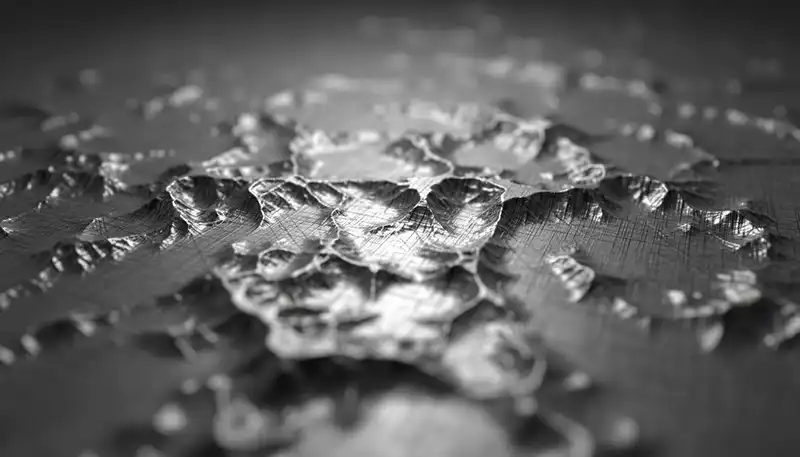
At first glance, a machined surface might look smooth. But under a microscope, it’s a landscape of peaks and valleys. Surface finish (also known as surface texture or surface roughness) is the measure of this textured topography.
Think of it like the grain of wood. Sometimes you want a rough, grippy texture (like a skateboard deck), and other times you need a glass-smooth surface (like a furniture tabletop). Metal parts are the same.
A surface profile is made up of:
-
Roughness (Ra/Rz): The fine, closely-spaced peaks and valleys from the manufacturing process itself (e.g., the cutting tool's mark).
-
Waviness (Wa/Wt): The more widely spaced undulations on the surface, usually caused by machine vibration or heat warping. Think of it as the "rolling hills" that the roughness sits on top of.
-
Lay: The dominant direction of the surface pattern, like the "grain."
Why is Surface Finish So Important in Engineering?
Specifying the right surface finish isn't about being picky; it's about function, cost, and performance.
- Fatigue Life: A rough surface is full of microscopic cracks and stress concentrators. A smoother finish significantly improves a part's resistance to fatigue and cracking under repeated loads.
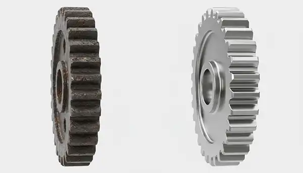
- Wear and Friction: Two rough surfaces sliding against each other will wear out quickly. A controlled, smooth finish reduces friction and wear, extending the life of moving parts.
- Sealing: Whether it's a hydraulic piston or a flange face, a surface that's too rough will leak fluid or gas. A surface that's too smooth might not retain lubrication. The "right" finish creates a perfect seal.
- Coating and Adhesion: Paints and coatings adhere much better to a surface with a specific, controlled roughness.
- Aesthetics: Let's be honest - a part with a uniform, attractive finish just looks more professional.
Surface Roughness Parameters: Ra, Rz, Rq and Rmax
You'll see letters like Ra and Rz on engineering drawings. These are parameters that give a number to the roughness. Here are the key players:
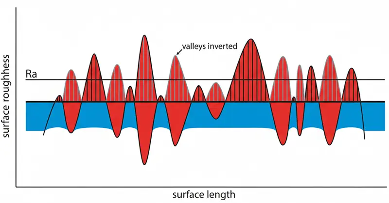
Ra - Arithmetic Average Roughness
Ra is the most common parameter. It calculates the average of the absolute values of the profile heights over a length.
- Simple Explanation: Imagine drawing a line through the middle of your surface profile. Ra is the average distance between that center line and all the peaks and valleys. It tells you how "bumpy" the surface is on average.
- What It Misses: Because Ra averages everything, it doesn't distinguish between a surface with a few sharp spikes and one with many gentle undulations. Both could have the same Ra value.
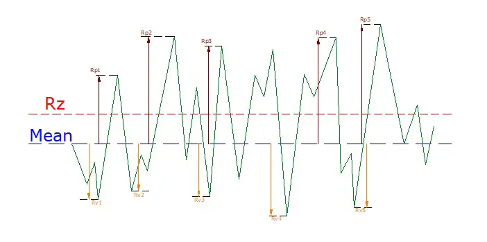
Rz - Average Maximum Height
While Ra looks at the average across the entire profile, Rz focuses on the extremes. It measures the average distance between the five highest peaks, Rp (Maximum Profile Peak Height) and the five deepest valleys Rv (Maximum Profile Valley Depth) within the sampling length.
- Why It Matters: Two surfaces can have identical Ra values, but very different Rz values. One might have occasional deep scratches that Rz will catch, while Ra smooths them out.
- When to Use It: Rz is critical for sealing applications (where deep valleys could cause leaks), for parts subject to fatigue (where deep scratches become crack starting points), and for surfaces that must maintain a lubricant film.
Rz - Average Maximum Height
Rq - Root Mean Square Roughness
Rq (also called RMS in older standards) is similar to Ra but mathematically more sensitive. Instead of taking the simple average of deviations, it squares each value, averages them, then takes the square root.
- The Difference: Squaring the values gives more weight to larger deviations from the mean line. So if your surface has occasional high peaks or deep valleys, Rq will show a higher number than Ra, highlighting those outliers.
- Historical Context: Many older drawings, especially from aerospace and defense industries, specify "RMS" rather than Ra. Today, Rq is the modern equivalent, though the terms are often used interchangeably in practice.
- When to Use It: Rq is valuable for optical surfaces, sealing applications, and anywhere that extreme peaks or valleys could compromise function.
Rmax - Maximum Roughness Depth
Rmax is the most straightforward parameter. It simply identifies the single largest peak-to-valley distance within the entire evaluation length.
- What It Tells You: Rmax answers the question, "What's the deepest scratch or highest burr on this surface?" It's a worst-case measurement.
- When It's Critical: For highly stressed components like turbine blades, medical implants, or precision bearings, a single deep scratch could cause catastrophic failure. Rmax ensures no defect exceeds the allowable limit.
- Important Note: Because Rmax only looks at one extreme event, it's less statistically stable than Ra or Rz. A single speck of dust or a momentary tool vibration can spike Rmax, even if the overall surface quality is excellent. For this reason, it's often used alongside Ra or Rz rather than alone.
| Parameter | What It Measures | Best For |
|---|---|---|
| Ra | The average roughness over the evaluation length | General‑purpose surface specification; most common callout |
| Rz | The average peak‑to‑valley height over several sampling lengths | Applications where extremes matter (sealing, stress‑critical areas) |
| Rq | Root mean square (RMS) roughness | Legacy specs, comparison with older drawings |
| Rmax | The single largest peak‑to‑valley height | Critical surfaces where no large defects are allowed |
How to Choose the Right Parameter
- Start with Ra for 90% of applications. It's universally understood, easy to measure, and correlates well with most manufacturing processes.
- Add Rz when the surface must seal against fluids or gases, or when the part will experience cyclic loading.
- Consider Rq for high-precision optical or bearing surfaces where the "average" doesn't tell the whole story.
- Specify Rmax only when absolutely necessary, and always pair it with Ra or Rz to provide context.
| Designing a Part With Critical Surface Requirements? Surface finish affects everything from sealing to fatigue life. Upload your drawing, and our manufacturing engineers will review your surface callouts - no charge. |
How to Measure Surface Roughness
You can't manage what you can't measure. Surface roughness is quantified using precise instruments.
The Various Methods of Measurement
-
Contact Profilometer: This is the most common method. A very fine, diamond-tipped stylus is dragged across the surface. As it moves over the peaks and valleys, the stylus's vertical movement is recorded and converted into a roughness value.
-
Pros: Accurate, reliable, and the established standard.
-
Cons: Can be slow and the delicate stylus can be damaged.

-
-
Non-Contact Profilometer: These use optical techniques like lasers or white light interferometry to map the surface without touching it.
-
Pros: Extremely fast and perfect for soft or delicate surfaces that a stylus might scratch.
-
Cons: Can be more expensive and sometimes struggles with very shiny or transparent materials.
-
-
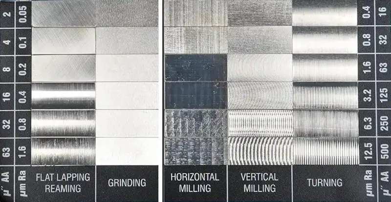
Comparative Sample Kits: This is a practical, low-tech method. The inspector has a set of physical samples with known roughness values. They compare the feel and look of the manufactured part to the samples by sight and touch (often with a fingernail).
-
Pros: Quick, inexpensive, and great for shop-floor checks.
-
Cons: Subjective and not suitable for critical inspection.
-
Understanding Cutoff Lengths (Sampling Length)
While Ra and Rz values tell you how rough a surface is, the cutoff length (often denoted as λc) tells the measurement instrument what to measure.
Think of a surface profile like a rolling landscape. You have tiny rocks (roughness) sitting on top of larger hills (waviness). The cutoff length acts as a filter:
- Shorter Cutoff (e.g., 0.08 mm or 0.25 mm): Filters out waviness to focus only on very fine roughness. Used for super-smooth surfaces like mirrors or honed cylinder bores.
- Standard Cutoff (0.8 mm): The industry standard for most machined parts (Ra 0.4 µm – Ra 3.2 µm). If no cutoff is specified on the drawing, 0.8 mm is the default.
- Longer Cutoff (2.5 mm or 8.0 mm): Used for rougher surfaces (like castings or flame-cut edges) to ensure the measurement averages out enough of the surface to be representative.
Why it matters: If you measure a rough surface with a cutoff that is too short, you will get an inaccurately low Ra value, potentially passing a bad part.
Surface Roughness Chart Symbols and Abbreviations
The symbols on an engineering drawing give a wealth of information beyond just a number.
Here’s a cheat sheet for the most common symbols:
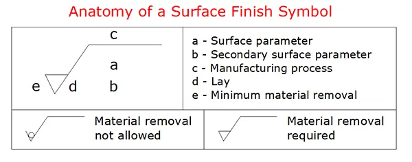
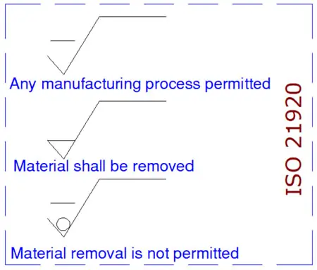
- Basic Symbol: The check mark (open V). It simply indicates that a surface has a specified texture requirement. The surface can be produced by any method (machining or non-machining).
- Circle in the V: A circle means "removal of material is not permitted". The surface must be left in its original state. This is exactly what you use to specify that a critical surface must keep its as-cast, as-forged, or as-molded finish without any secondary machining.
- Bar on the V: A horizontal bar means "material removal is required". Material removal can be by any process (milled, turned, grinding, EDM, etc.). An untouched as-cast, as-forged, or molded surface is not allowed here.
- Bar OVER the Left Leg of the V: Explicitly denotes an ISO 21920 Profile specification (distinguishing it from legacy standards and 3D area scans).
-
The Full Callout: Around the symbol, you'll find:
-
The roughness value (e.g., Ra 1.6)
-
The manufacturing process (e.g., "Grind"), if specified.
-
The lay direction (see below).
-
The sampling length.
-
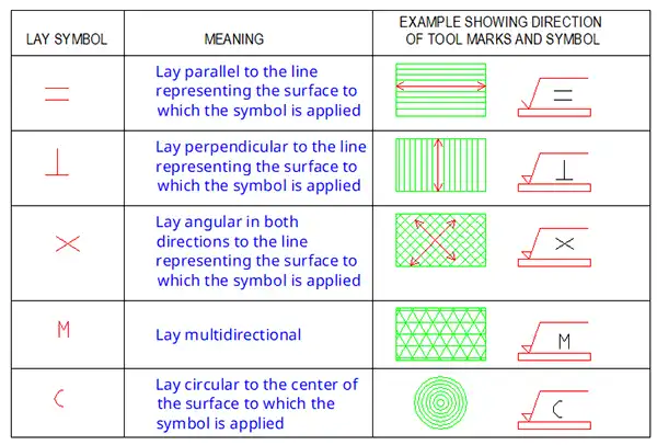
Lay Direction Symbols
The lay is the direction of the predominant surface pattern, and it's represented by a symbol inside the check mark.
The Surface Roughness Chart
This chart links common Ra values to their typical appearance, manufacturing process, and application.
| Ra (µm) | Ra (µin) | Appearance | Typical Process | Application Examples |
|---|---|---|---|---|
| 25 | 1000 | Very rough | Saw cutting, rough forging | Unfinished parts, non-critical surfaces |
| 12.5 | 500 | Rough | Rough machining, drilling | Non-mating surfaces, rough stock |
| 6.3 | 250 | Clearly visible tool marks | Standard milling, turning | Non-critical bearing surfaces, bolt holes |
| 3.2 | 125 | Visible tool marks | General machining | Parts under stress, sliding surfaces |
| 1.6 | 63 | Smooth, slight marks | Precision machining, reaming | Hydraulic cylinders, bearing seats |
| 0.8 | 32 | Very smooth, no visible marks | Grinding, honing | Gears, crankshafts, precise sliding parts |
| 0.4 | 16 | Near‑mirror finish | Precision grinding, lapping | Ball bearings, precision instruments |
| 0.2 | 8 | Mirror‑like finish | Polishing, superfinishing | Optical components, gauge blocks |
Surface Finish Conversion Chart
Need to convert between Ra, Rz, and other parameters? Use this chart as a guide. Important Note: These are approximations, as Ra and Rz measure different things. For critical applications, always refer to the primary standard.
| Ra (µm) | Ra (µin) | Rz (µm) approx. | ISO Grade Number |
|---|---|---|---|
| 0.025 | 1 | 0.1 | N1 |
| 0.05 | 2 | 0.2 | N2 |
| 0.1 | 4 | 0.4 | N3 |
| 0.2 | 8 | 0.8 | N4 |
| 0.4 | 16 | 1.6 | N5 |
| 0.8 | 32 | 3.2 | N6 |
| 1.6 | 63 | 6.3 | N7 |
| 3.2 | 125 | 12.5 | N8 |
| 6.3 | 250 | 25 | N9 |
| 12.5 | 500 | 50 | N10 |
| 25 | 1000 | 100 | N11 |
Surface Roughness Comparison Guide: Choosing the Right Finish
This is where theory meets practice. How do you choose?
-
For a Static Gasket Seal: You need a flat surface with just enough "bite." A finish that is too smooth can be as bad as one that is too rough. A range of Ra 1.6 - 3.2 µm is often ideal.
-
For a Rotating Shaft in a Bearing: A very smooth finish is needed to prevent wear and heat buildup. Aim for Ra 0.4 - 0.8 µm.
-
For a Structural Weldment: A non-critical surface that will be painted. A finish of Ra 6.3 - 12.5 µm is perfectly acceptable and cost-effective.
The Golden Rule: Always specify the roughest finish that will perform the required function.A smoother finish always means more machining time, specialized processes, and higher cost. Moving from Ra 3.2 to Ra 0.8 could easily double the cost of that surface's machining.
Your Surface Roughness Chart Cheat Sheet
Let's condense everything into a few key takeaways:
-
Start with Ra: For most applications, specifying Ra is sufficient.
-
Know Your Numbers:
-
Ra 3.2 µm: Your standard, go-to machined finish.
-
Ra 1.6 µm: A high-quality finish for mating surfaces.
-
Ra 0.8 µm: A precision finish for dynamic components.
-
-
Understand the Symbols: A circle in the symbol means “must be machined by material removal.” The basic check mark means a surface requirement exists, even if the process is not specified.
-
Consider the Cost: Every step down in roughness value is a step up in price.
Conclusion
Mastering surface roughness is a superpower in mechanical design and manufacturing. It is the difference between a part that works and a part that excels. By using this guide, the charts, and the cheat sheet, you can now specify surface finishes with confidence, ensuring your designs are not only functional but also efficient and cost-effective to produce.
Frequently Asked Questions
What is the difference between Ra and Rz?
Ra is an average height, while Rz is the average maximum peak-to-valley height. Ra gives a general picture, while Rz is better at capturing extreme variations.
What is a "standard" surface finish for CNC machining?
For most CNC milling and turning, a finish of Ra 3.2 µm is considered standard and is achievable directly from the tool without secondary operations.
Can I perfectly convert Ra to Rz?
No. The conversion is not a perfect 1:1 ratio because they measure different geometric properties. The charts provide close approximations, but for critical features, you should specify and measure the exact parameter you need.
What does a surface finish of 0.8 mean?
It means an Ra value of 0.8 micrometers (µm). This is a very smooth, high-precision finish typically achieved by grinding or honing.
Can different surfaces of the same part have different finishes?
Yes, and this is actually very common in manufacturing. Different surfaces on the same part often require different finishes based on their function. For example, a shaft might need Ra 0.8 µm on the journal surfaces that contact bearings for smooth rotation, Ra 3.2 µm on mounting faces that need good sealing, and Ra 6.3 µm on non-critical exterior surfaces. Specifying different finishes saves money by only applying tighter (more expensive) finishes where functionally necessary. On your drawing, simply place the appropriate surface finish symbol on each surface or use a general note like "Ra 6.3 unless otherwise specified" with specific callouts where finer finishes are needed.
What is the difference between surface finish and tolerance?
Surface finish and tolerance are two distinct specifications that control different aspects of a part. Tolerance defines how much a dimension can vary from its nominal value (for example, 50mm ±0.1mm controls size), while surface finish describes the texture or roughness of the surface itself (for example, Ra 3.2 µm controls smoothness). You can have a part that's within dimensional tolerance but has the wrong surface finish, or vice versa. Both are specified independently on engineering drawings - tolerances appear next to dimensions, while surface finish symbols appear on or near the surface features they control.