Introduction
Ceramic CNC machining makes it possible to turn extremely hard, brittle technical ceramics into precise, repeatable components for demanding applications in electronics, aerospace, medical devices and more. Compared with metals or plastics, ceramics offer outstanding wear, temperature and electrical properties, but they demand very different machining strategies.
Engineers who understand how ceramic CNC machining works, which materials to choose and how to design around the material’s brittleness can avoid costly scrap, schedule risk and unexpected performance issues.
If you’ve ever tried to machine a ceramic part, you know it’s nothing like cutting aluminum or steel. Ceramics are hard, brittle, and unforgiving - yet they offer properties that metals simply can’t match: extreme heat resistance, electrical insulation, and wear life that lasts for years. That’s where ceramic CNC machining comes in. It’s the art and science of turning advanced ceramic materials into high-precision components using computer‑controlled tools.
In this guide, we’ll dive deep into the technical side of ceramic CNC machining. Whether you’re an engineer designing next‑gen medical implants, a buyer sourcing semiconductor components, or a machinist looking to expand your skills, you’ll find detailed tables, process insights, and answers to the most common questions.
What Is Ceramic CNC Machining?
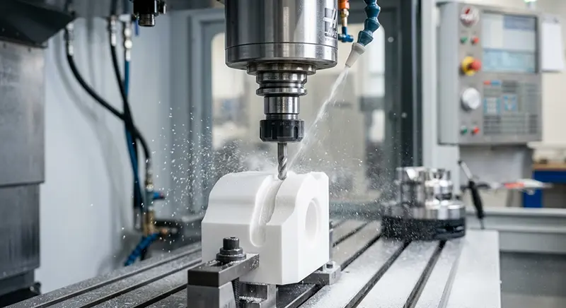
Ceramic CNC machining is a subtractive manufacturing process where computer‑controlled machines (mills, lathes, grinders) remove material from a ceramic workpiece to create a finished part. Because ceramics are among the hardest materials on earth, the process requires specialized tools - usually diamond or cubic boron nitride-and extremely precise control of speeds, feeds, and cooling.
Unlike metals, ceramics don’t deform plastically. They either remain intact or crack. This binary behavior makes machining them a high‑stakes operation. But when done correctly, the results are components with tolerances as tight as ±0.005 mm and surface finishes that can reach mirror‑like quality without secondary polishing.
Why Ceramics Are So Difficult to Machine
To appreciate ceramic CNC machining, you have to understand the material’s personality:
- Extreme hardness: Most technical ceramics rank 8-9.5 on the Mohs scale. Diamond (10) is often the only tool material that can cut them efficiently.
- Brittleness: There’s no “give.” If the cutting force exceeds the material’s fracture toughness, the part will chip or shatter instantly.
- Poor thermal conductivity: Heat generated during cutting stays concentrated near the tool edge, creating thermal stresses that can cause micro‑cracks.
- High wear resistance: The same property that makes ceramics great for bearings also means they wear out conventional tools quickly.
These challenges demand a completely different mindset than metalworking. Instead of thinking in terms of “chip formation,” machinists think in terms of “controlled fracture” and “ductile‑mode removal.”
|
Working with technical ceramics like alumina or zirconia? Clarwe machines sintered and green-state ceramics to tolerances as tight as ±0.005 mm.Get a Ceramic Machining Quote → |
Common Ceramic Materials for CNC Machining
Choosing the right ceramic is the first critical step. Below is a detailed table of the most frequently machined technical ceramics, their properties, and typical applications.
| Material | Hardness (HV) | Fracture Toughness (MPa·m½) | Thermal Conductivity (W/m·K) | Key Characteristics |
|---|---|---|---|---|
| Alumina (Al₂O₃) | 1800-2200 | 3-4 | 20-30 | High wear resistance, excellent electrical insulation, cost‑effective |
| Zirconia (ZrO₂) | 1200-1300 | 9-10 | 2-3 | Highest toughness among ceramics, biocompatible, white appearance |
| Silicon Nitride (Si₃N₄) | 1500–1800 | 6-8 | 30-35 | Lightweight, high strength, thermal shock resistant |
| Silicon Carbide (SiC) | 2500–2800 | 3-4 | 120-170 | Extremely hard, excellent thermal conductivity, corrosion resistant |
| Aluminum Nitride (AlN) | 1000-1200 | 2-3 | 170-200 | High thermal conductivity, electrical insulator, matched CTE to silicon |
| Macor® (Machinable Glass Ceramic) | 600-700 | 1-2 | 1.5 | Can be machined with standard carbide tools; no post‑sintering shrinkage |
|
Not sure which ceramic is right for your application? Clarwe's engineers work with alumina, zirconia, silicon carbide, silicon nitride, aluminum nitride, and Macor. Upload your drawing and we'll confirm machinability and tolerances before you commit. |
Green‑State vs. Hard‑State Machining
One of the most important decisions in ceramic CNC machining is whether to cut the material before or after it’s fully sintered (fired). Each approach has its own advantages.
Green‑State Machining (Pre‑Sintering)
In this stage, the ceramic is in a “chalk‑like” or partially densified state. Because it’s softer, you can use carbide tools and achieve much higher material removal rates. Complex features like thin walls or internal threads are easier to produce without cracking.
However, you must account for shrinkage during the subsequent sintering process-typically 15–25% linear. That means every dimension on your CAD model must be scaled up. The final part will have good dimensional accuracy, but not the sub‑micron precision possible with hard machining.
Hard‑State Machining (Post‑Sintering)
Here, the ceramic is fully densified and has reached its ultimate hardness. This is where the tightest tolerances (±0.005 mm) and best surface finishes are achieved. The downside? You’re now cutting a material that’s nearly as hard as diamond. Diamond tooling is mandatory, speeds are slower, and cycle times are longer.
Hard‑state machining is the go‑to choice for final‑use components where dimensional stability is critical and no shrinkage is acceptable.
| Green-state or hard-state — Clarwe handles both.
Tell us your tolerance requirements and we'll recommend the right machining route for your ceramic part.
|
CNC Processes for Ceramics
Different operations call for different techniques. Here’s how the most common CNC processes are adapted for ceramics.
1. CNC Milling
Milling is used for complex 3D geometries—pockets, slots, and contours. Diamond‑coated end mills are standard. To avoid chipping, tool paths often use trochoidal milling or constant engagement strategies to keep cutting forces steady.
2. CNC Grinding
Grinding is the workhorse for achieving tight tolerances and fine surface finishes. Diamond grinding wheels (often resin‑bonded or metal‑bonded) are used. Surface grinding, cylindrical grinding, and jig grinding are all common. With the right parameters, you can achieve surface finishes of Ra 0.2 µm or better.
3. 5‑Axis Machining
Five‑axis CNC machining allows the tool to approach the part from nearly any angle. This is especially valuable for ceramics because it lets you keep the tool engaged optimally, reducing stress on the part and allowing complex undercuts and angled features that would be impossible with 3‑axis.
4. Ultrasonic‑Assisted Machining (UAM)
UAM adds high‑frequency vibrations (20–40 kHz) to the cutting tool. These micro‑oscillations help break chips more efficiently and reduce cutting forces, making it particularly useful for brittle materials like ceramics. UAM can extend tool life and enable higher material removal rates.
5. Laser Cutting & Ablation
For thin ceramics or when mechanical contact is risky, laser cutting offers a non‑contact alternative. Fiber lasers and picosecond lasers can cut intricate shapes with minimal heat‑affected zones. However, laser processing is generally limited to thin sections and may leave a recast layer that needs to be removed.
Critical Machining Parameters
When machining sintered ceramics, the parameters look very different from metal cutting. Below is a typical starting point for a diamond‑coated end mill on zirconia or alumina:
| Parameter | Recommended Range | Why |
|---|---|---|
| Spindle Speed | 20,000 – 60,000 RPM | High speed keeps chip load low and reduces cutting forces. |
| Feed Rate | 50 – 300 mm/min | Conservative feed rates prevent tool deflection and sudden force spikes. |
| Depth of Cut (Axial) | 0.01 – 0.05 mm | Multiple light passes are far safer than a single deep cut. |
| Stepover (Radial) | 0.02 – 0.1 mm | Small stepovers minimize radial engagement and tool deflection. |
| Coolant Strategy |
Hard-state: Flood coolant (water-soluble, low pressure) or MQL preferred. Green-state: Dry machining with vacuum extraction only. |
Flood coolant is appropriate and recommended for sintered (hard-state) ceramics — it stabilizes cutting temperatures, captures abrasive ceramic dust, and prevents micro-crack propagation from heat buildup. For green-state (pre-sintered) ceramics, liquid coolant must be avoided entirely as moisture causes swelling, dimensional distortion, and structural weakening of the unfired biscuit . |
Dimensional Tolerances and Surface Finish Standards
One of the most frequent questions we hear: “How accurate can ceramic CNC machining really be?”
With proper fixturing and tooling, hard‑state machining routinely achieves:
- Dimensional tolerances: ±0.005 mm to ±0.010 mm (5-10 µm)
- Surface finish: Ra 0.2 – 0.4 µm for ground surfaces; Ra 0.05 µm possible with ductile‑mode grinding or lapping
- Flatness: ≤ 0.002 mm per 25 mm (0.00008 in/in) for polished substrates
For green‑state machining, the achievable tolerances are limited by the sintering shrinkage uniformity, usually around ±0.1 mm after firing unless the part is subsequently hard‑machined.
|
CLARWE CERAMIC MACHINING CAPABILITIES
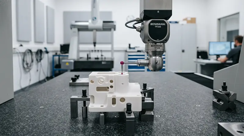
✓ Tolerances to ±0.005 mm on hard-state ceramics . ✓ Surface finish to Ra 0.2 µm via precision grinding
✓ CMM inspection & full dimensional reports available . ✓ AS9100D | ISO 9001:2015 | ISO 13485:2016 certified
|
Practical Advice for Engineers and Designers
When specifying tolerances for ceramic CNC machined parts, keep these guidelines in mind:
- Only tighten what matters. If a feature doesn't require ±0.005 mm (±5 µm) tolerance, don't specify it. Looser tolerances can reduce cost and lead time significantly.
- Consider green-state vs. hard-state trade-offs. For complex geometries with moderate tolerance requirements, green-state machining followed by sintering may be more economical. For high‑precision fits and final‑use surfaces, hard-state machining is non‑negotiable.
- Communicate functional requirements. If the part will be lapped after machining, the as‑machined surface finish may be less critical. If the part requires a specific sealing surface, specify both the finish and flatness.
- Partner with experienced manufacturers. Not every CNC shop is equipped for ceramic machining. Look for facilities with high‑speed spindles, diamond tooling expertise, and a demonstrated track record with your specific ceramic material.
Industry Applications
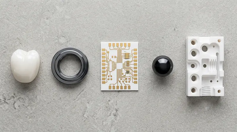
Ceramic CNC machining is not a niche curiosity-it’s a critical enabler in several high‑tech industries.
| Industry | Components | Why Ceramics |
|---|---|---|
| Aerospace & Defense | Turbine engine seals, thermal protection tiles, radomes, missile guidance housings | Lightweight, withstand extreme temperatures (up to 1600°C), and resist oxidation |
| Medical & Dental | Zirconia dental implants, hip and knee replacements, surgical instruments, bone screws | Biocompatible, corrosion‑free, non‑metallic for MRI compatibility |
| Semiconductor & Electronics | Wafer handling arms, electrostatic chucks, heat sinks, plasma‑resistant chamber parts | High purity, electrical insulation, thermal management, and chemical inertness |
| Industrial Machinery | Wear plates, nozzles, valves, high‑precision metrology bases | Exceptional wear life, dimensional stability, and resistance to aggressive chemicals |
What's Next in Ceramic CNC Machining?
The field is evolving rapidly. Here are three developments that are changing the game.
1. Ductile‑Mode Machining
By using ultra‑high spindle speeds (up to 80,000 RPM) and extremely small depths of cut, it’s possible to remove ceramic material in a “plastic” (ductile) regime rather than by brittle fracture. This yields mirror‑like finishes directly from the machining process, eliminating the need for separate lapping or polishing steps. This is already being implemented on high‑end 5‑axis machines.
2. Hybrid Manufacturing (Additive + Subtractive)
Combining ceramic 3D printing with CNC finishing allows the creation of parts with internal lattice structures that would be impossible to machine from a solid block. The printed “near‑net” shape is then finish‑machined to precise tolerances. This approach reduces material waste and can shorten lead times for complex prototypes.
3. AI‑Driven Process Optimization
Machine learning algorithms are being integrated into CNC controllers to monitor vibration, acoustic emissions, and spindle load in real time. The system can then adjust feeds and speeds automatically to prevent chipping or tool failure. Early adopters report 20% longer tool life and a significant reduction in scrap rates.
Conclusion
Ceramic CNC machining is a specialized discipline that blends material science, precision engineering, and a deep respect for the brittle nature of advanced ceramics. While it presents unique challenges - tool wear, thermal management, and the risk of chipping - the rewards are components that outperform metals in the most demanding environments.
Whether you’re working with alumina for high‑voltage insulators, zirconia for medical implants, or silicon carbide for semiconductor processing, the principles remain the same: rigid machines, diamond tooling, conservative parameters, and a clear understanding of the material’s behavior.
As technology advances, we’re seeing new possibilities - ductile‑mode cutting, hybrid additive/subtractive processes, and AI‑driven optimization - that are making ceramic machining more capable and cost‑effective than ever. For those who master it, the ability to turn a block of ceramic into a precision component is not just a manufacturing skill; it’s a gateway to solving some of the toughest engineering problems in the world.
Frequently Asked Questions
Can you machine ceramic on a standard CNC mill?
It’s not recommended. Standard mills lack the rigidity and vibration damping required for ceramic machining. Even if you install a diamond tool, the machine’s vibration can cause micro‑chipping. Specialized machines with high‑speed spindles and heavy bases are the safe choice.
What’s the best tool material for ceramic machining?
For sintered ceramics, diamond (PCD, diamond‑coated, or diamond grinding wheels) is the only practical option. Cubic boron nitride (CBN) can be used for some ferrous ceramics but is less common. For green‑state ceramics, carbide tools work well.
How do you avoid cracking during machining?
- Use extremely shallow depths of cut.
- Maintain constant tool engagement (avoid sudden plunges).
- Use mist or air cooling—never shock the part with flood coolant.
- Fixture the part securely with even pressure; avoid point loads.
Is it better to machine green or hard?
It depends on your priorities. If you need tight tolerances and a finished part ready to use, go with hard‑state machining. If you’re making complex shapes, need faster cycle times, and can accommodate shrinkage, green‑state machining is often more economical.
What surface finish can I expect without lapping?
With precision grinding, you can achieve Ra 0.2–0.4 µm. With ductile‑mode milling, Ra 0.05 µm is possible. If you need optical quality (Ra < 0.01 µm), lapping or polishing is still required.
|
Ready to machine your ceramic part?
Upload your drawing — our engineers will review your geometry, recommend the right ceramic and process route, and send you a detailed quote within 2 hours.
|