What is CNC Milling?
CNC milling is a manufacturing process that uses computer-controlled rotary cutting tools to remove material from a workpiece. The term “CNC” stands for Computer Numerical Control, meaning the machine’s movements are precisely guided by digital instructions.
The CNC machining process generally involves three main steps. First, the engineer creates a CAD model of the desired part. Next, the machinist converts this digital design into a CNC program (G-code) and prepares the machine for operation. Finally, the CNC system automatically performs the machining tasks with minimal human intervention, cutting away material to produce the finished component.
CNC milling machines can create complex shapes and features with high accuracy and repeatability. The process involves operations like drilling, slotting, contouring, andfacing on materials such as metal, plastic, or wood. Multi-axis CNC mills, such as 3-axis, 4-axis, and 5-axis machines, allow for machining from multiple angles without repositioning the part.
A key advantage of CNC milling is its ability to produce consistent, high-quality parts for both prototypes and mass production. CNC milling is widely used in industries such as aerospace, automotive, medical, and electronics for precision component manufacturing.
Types of CNC Milling Machines
CNC milling machines come in various configurations, each offering different levels of precision, flexibility, and complexity. The number of axes a machine can control determines how the cutting tool interacts with the workpiece during machining. Below are three common types of CNC milling machines, each suited for specific manufacturing needs and part geometries.
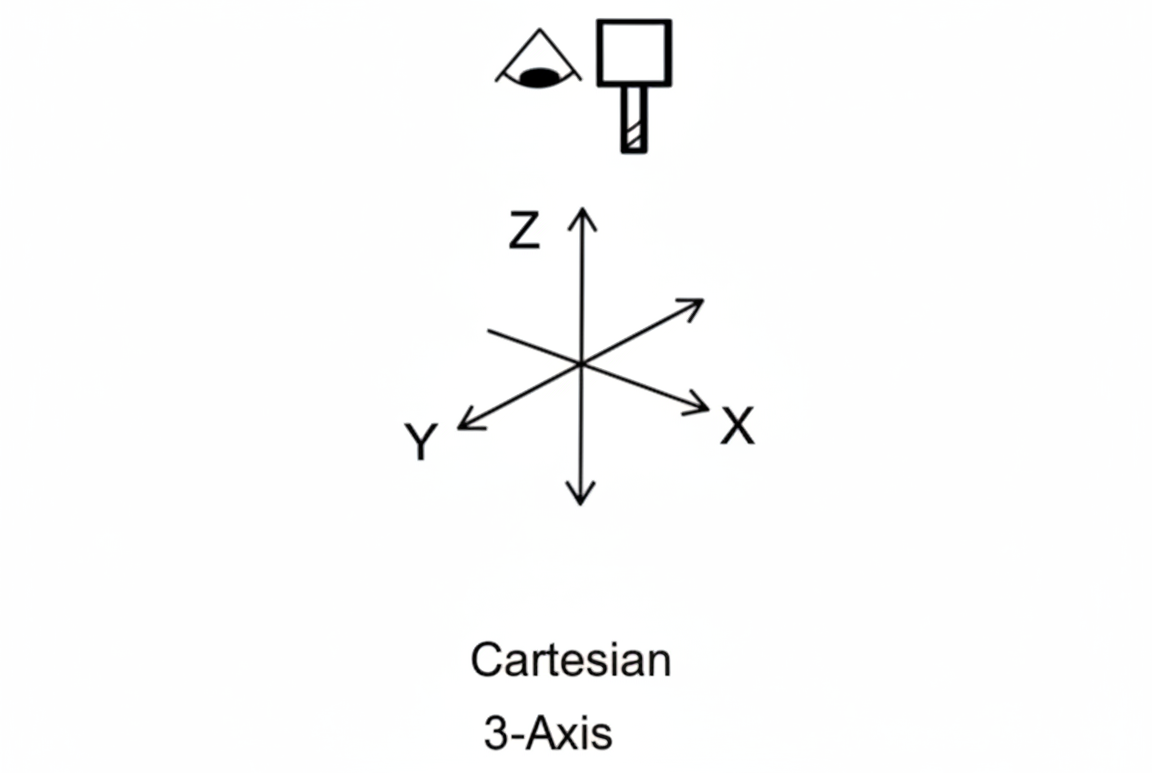
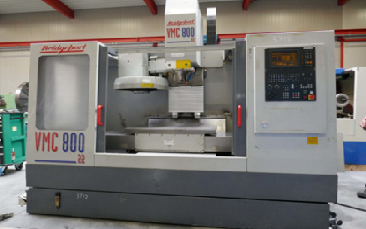
3-axis CNC Milling Machine
A 3-axis CNC milling machine moves the cutting tool along the X, Y, and Z axes to machine a stationary workpiece. It is ideal for simple geometries, flat surfaces, and basic contours. Although precise and efficient, it cannot easily machine complex shapes that require access from multiple angles.
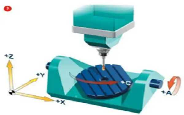
Indexed 3 + 2 Axes CNC Milling Machine
An indexed 3 + 2 axis machine allows the cutting tool to be locked at a fixed angle using two additional rotary axes. The machining then occurs using standard 3-axis movements while the part remains tilted in a specific orientation. This setup improves access to angled features and reduces repositioning, though it doesn’t allow simultaneous multi-axis motion.
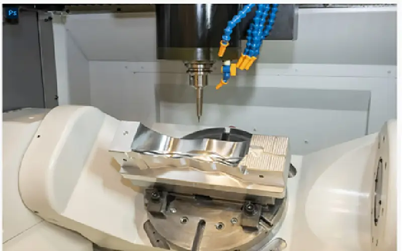
Continuous 5-Axis CNC Milling Machine
A continuous 5-axis CNC milling machine moves all five axes (X, Y, Z, A, and B/C) simultaneously. It enables the creation of highly complex parts with smooth curves and contours in a single setup. This type of machine is widely used in aerospace, medical, and automotive industries for high-precision, intricate components.
| Feature / Capability | 3-Axis CNC Machine | Indexed 3+2 Axis CNC Machine | Continuous 5-Axis CNC Machine |
|---|---|---|---|
| Axes of Motion | Linear X, Y, Z | Linear X, Y, Z + two rotational axes (A/B or B/C) indexed only | Linear X, Y, Z + two rotational axes simultaneously controlled |
| Rotary Axes Behaviour | Not available | Locked during cutting; reorients the part between operations | Fully synchronized with linear axes during cutting |
| Complex Geometry Capability | Low-moderate | Moderate–high (multi-face machining) | Very high (full 5-axis contouring, complex aerospace/medical surfaces) |
| Typical Use Cases | Prismatic parts, pockets, slots, simple contours | Parts requiring machining on multiple faces without refixturing; angled holes; turbine housings | Blisks, impellers, molds with compound curves, orthopedic implants |
| Setup Time | Higher (multiple setups needed for multi-face work) | Lower than 3-axis (fewer setups due to positional tilting) | Lowest for complex parts; single setup for most geometries |
| Accuracy & Tolerance | Limited by manual repositioning and fixturing | High accuracy due to controlled indexing | Highest accuracy for free-form surfaces due to continuous orientation control |
| Surface Finish Quality | Good for planar surfaces; limited on complex angles | Better finish on angled surfaces due to proper tool orientation | Excellent finish on complex 3D surfaces with optimal tool-surface contact |
| Tool Access | Restricted; deep cavities require long tools | Improved access due to part reorientation | Maximum access, enabling short tools and reduced chatter |
| Programming Complexity | Low | Moderate (CAM-driven positional strategies) | High (requires advanced 5-axis CAM and collision avoidance) |
| Machine Cost | Lowest | Medium | Highest |
| Ideal for | General machining shops | High-mix precision machining | High-value industries: aerospace, medical, energy, automotive prototype |
CNC Milling Machine Selection Tips
| Use Case | Recommended Machining Process |
|---|---|
| Simple prismatic parts (e.g., brackets, plates, enclosures) requiring machining on one or two sides | 3-Axis CNC Milling Machine |
| Multi-face parts that need machining on several orientations but do not require simultaneous movement of all axes (e.g., housings,molds, fixtures) | Indexed 3+2 Axis CNC Milling Machine |
| Complex geometries with continuous curves or surfaces requiring simultaneous multi-axis motion (e.g., turbine blades, impellers,orthopedic implants) | Continuous 5-Axis CNC Milling Machine |
| High-precision parts requiring machining from multiple angles with minimal setups and tight tolerances (e.g., aerospace or medical components) | Continuous 5-Axis CNC Milling Machine |
CNC Milling Process
Modern CNC mills use CAD/CAM software to convert 3D models into toolpaths for automated machining. The CNC milling process involves a sequence of precisely defined stages, starting from material preparation and ending with final post-processing.
Overview of the CNC Milling Workflow
- G-Code Generation: The machining G-code is created either from a CAD model supplied by the customer or derived manually from technical drawings by the operator. This code defines the exact toolpaths and machining parameters required for the milling operation.
- Material Preparation: The raw material (blank) is cut to the specified dimensions and firmly secured to the milling machine’s worktable. Proper alignment and clamping ensure accuracy and stability throughout the machining process.
- Roughing Passes: During the roughing stage, high-speed cutting tools remove large volumes of material to rapidly shape the part. This step focuses on efficiency rather than precision, using specialized roughing tools.
- Finishing Passes: Once roughing is complete, finishing passes are performed to achieve precise dimensions and a smooth surface finish. Smaller amounts of material are removed at lower feed rates to refine the final geometry.
- Deburring: After machining, the part is manually deburred to eliminate sharp edges, burrs, and other surface imperfections created during cutting.
- Dimensional Inspection: Critical features and dimensions are measured to verify that the part meets the required tolerances and quality specifications.
- Post-Processing: Finally, any additional treatments - such as surface finishing, coating, or heat treatment—are applied to enhance the part’s functionality, durability, or appearance.
CNC Cutting Tools for Milling
CNC cutting tools come in various types, each engineered for high-precision machining. The selection of a particular tool depends on the machining operation, project specifications, and the configuration of the CNC machine.
Common CNC Milling Cutting Tools
| Tool Type | Geometry / Key Features | Primary Machining Use | Tool Image |
|---|---|---|---|
| Flat End Mill | Flat cutting tip with sharp edges | Milling flat surfaces, pockets, and sharp corners with precise depth control. | 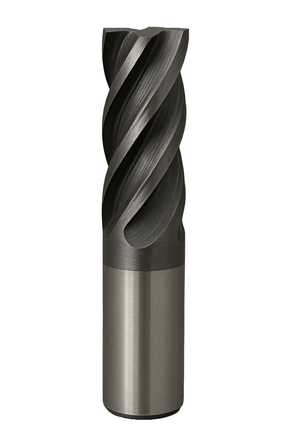 |
| Bull End Mill | Flat tip with a small corner radius | Contouring and finishing operations to reduce tool wear and improve surface quality. | 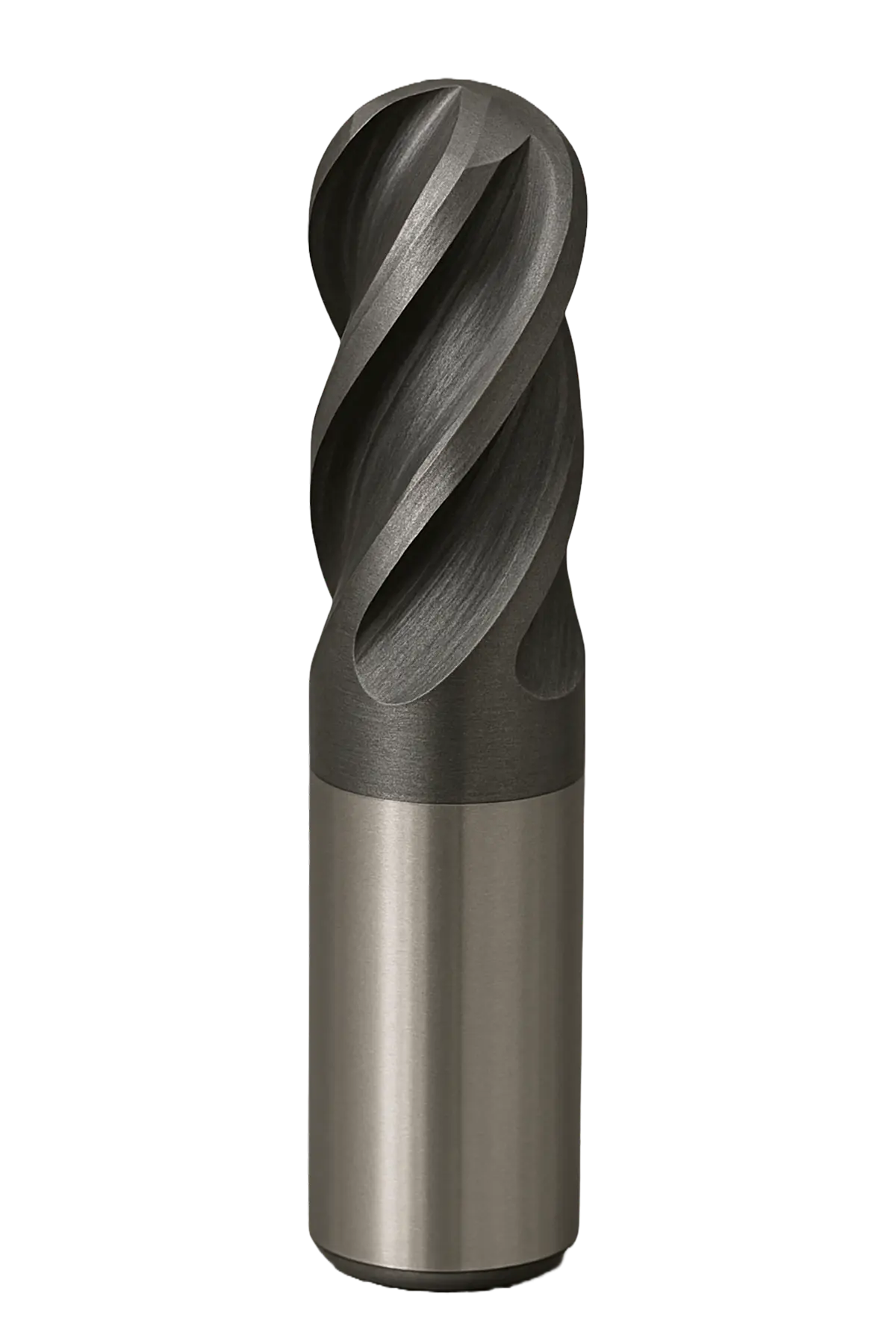 |
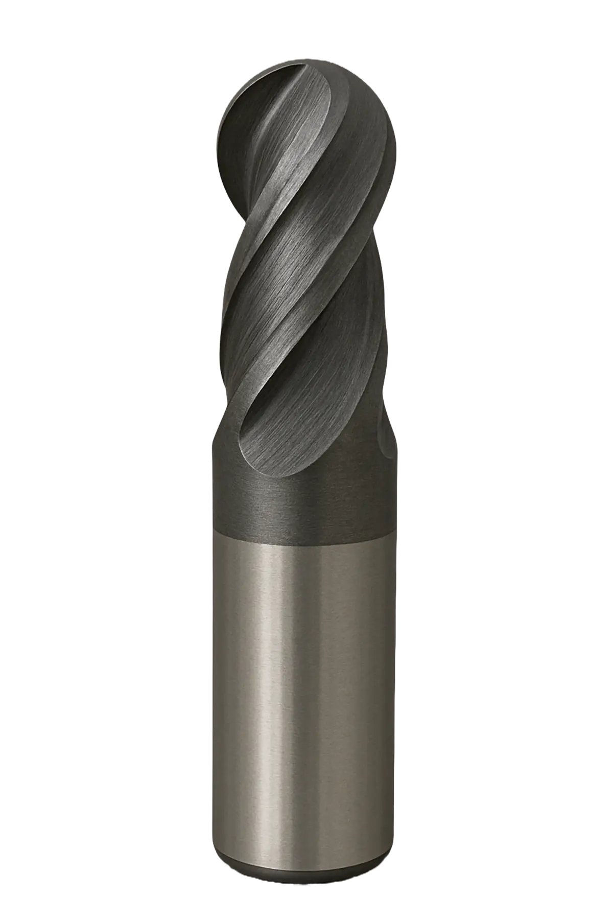
| Ball End Mill | Hemispherical tip | 3D contouring, sculpted surfaces, and complex geometries with smooth surface transitions |
 |
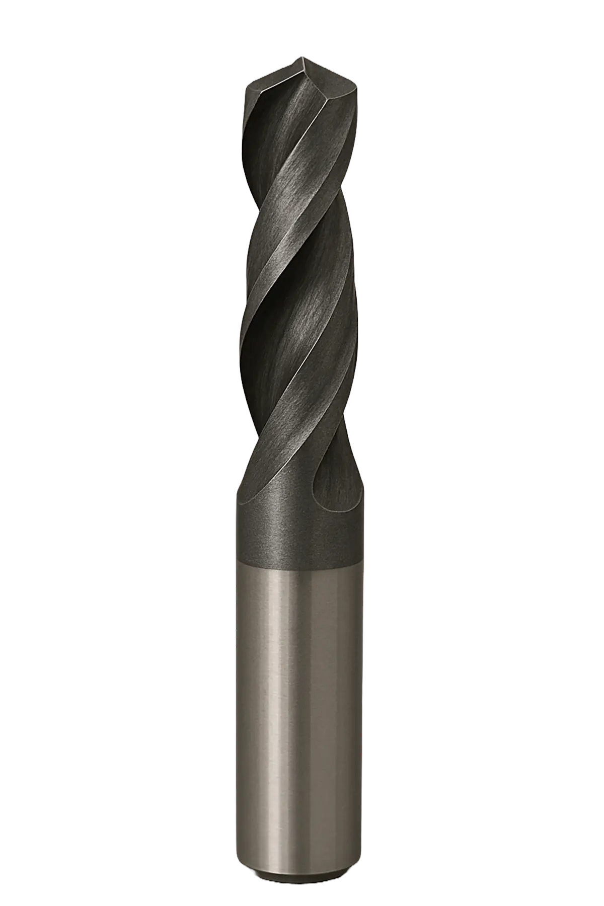
| Drill | Pointed tip with helical flutes |
Creating round holes by removing material axially. |
 |
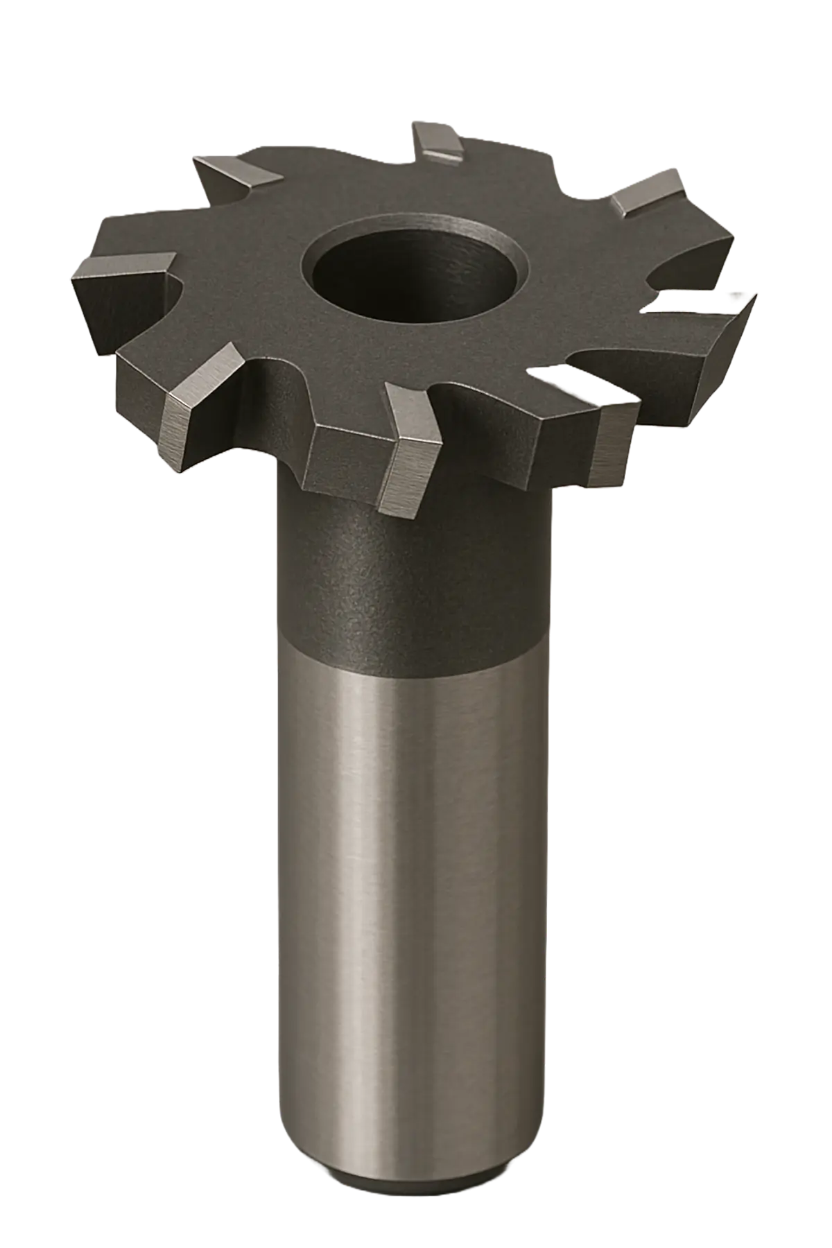
| Slot Cutter | Circular cutter with side-cutting edges |
Milling narrow slots, grooves, and keyways with accurate width and depth. |
 |
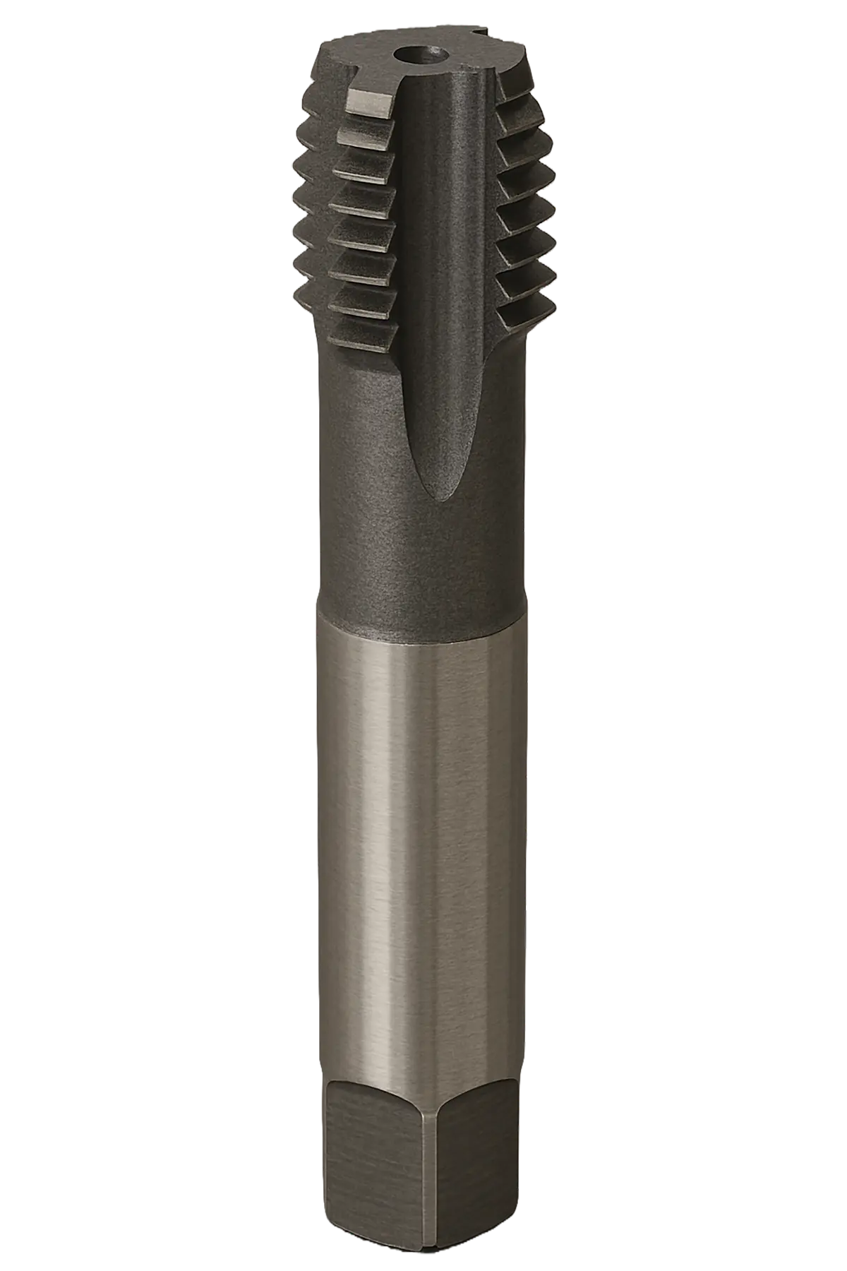
| Tap | Threaded tool for internal cutting |
Cutting or forming internal screw threads in pre-drilled holes. |
 |
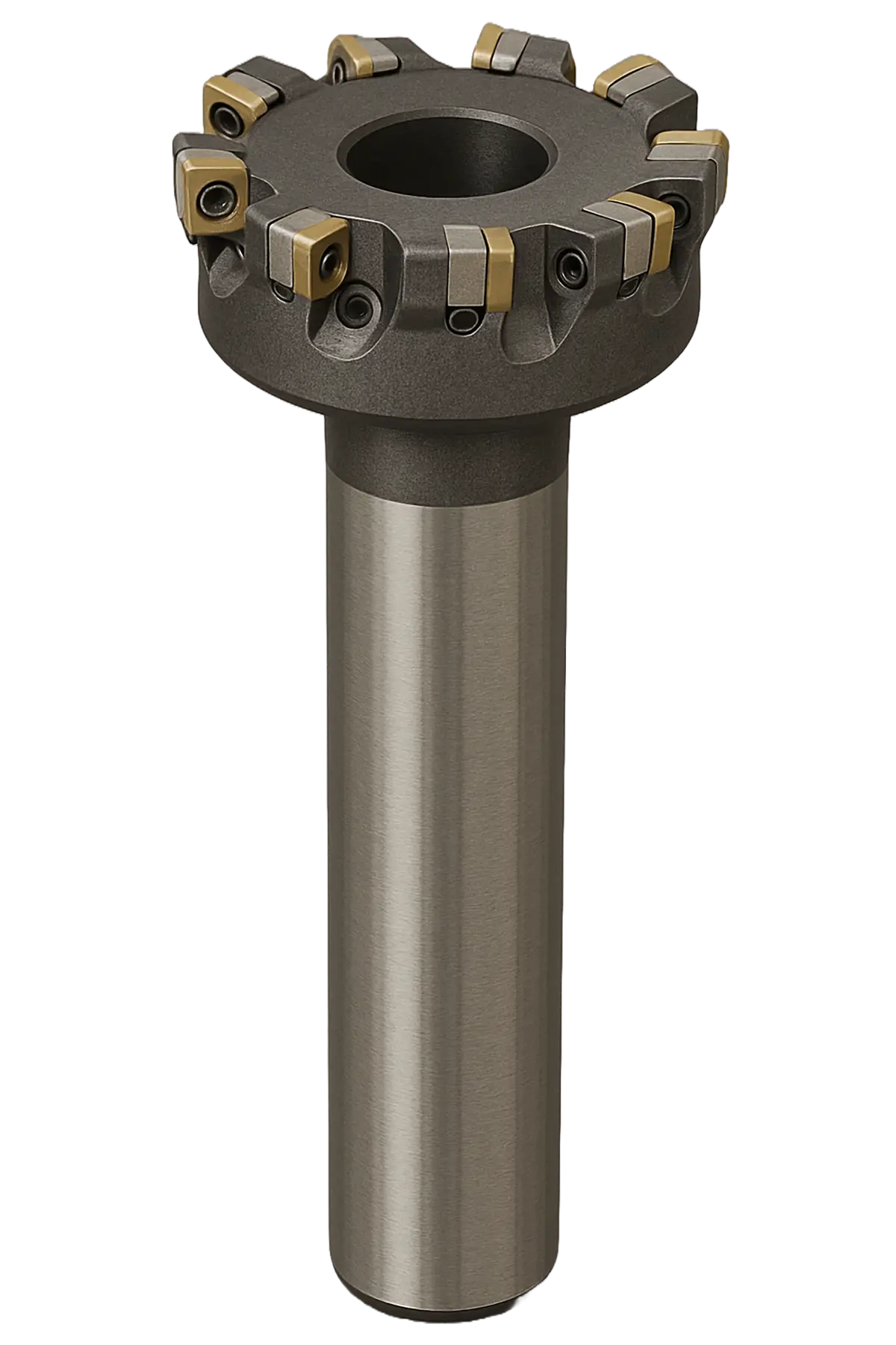
| Face Milling Cutter | Large-diameter tool with multiple inserts |
Machining large, flat surfaces quickly for a smooth, uniform finish. |
 |
Key CNC Milling Design Rules
| Feature | Recommended Minimum / Maximum | Design Guideline |
|---|---|---|
| Wall thickness (metals) | ≥ 1.0–1.5 mm | Use thicker walls to reduce chatter and deformation during milling |
| Wall thickness (plastics) | ≥ 1.5–2.0 mm | Increase wall thickness to compensate for lower stiffness inplastics |
| Internal corner radius | ≥ 1/3 cavity depth (e.g., ≥ 1 mm) | Add generous fillets so end mills can reach corners without multiple tiny tools |
| Pocket depth | ≤ 3× tool diameter | Keep pockets shallow relative to tool diameter for stability and lower cost |
| Hole diameter | ≥ 1.0 mm (standard drills) | Avoidvery small holes that require special micro-tools and slowfeeds |
| Hole depth (drilled) | ≤ 6× hole diameter | Deeper holes are possible but more expensive; use both-side drilling if needed |
| Thread size | ≥ M2 or #2 | Very small threads are harder to machine and inspect; avoid when possible |
| Thread length | ≤ 3× nominal diameter | Longer threads add cost with little strength benefit beyond 3×diameter |
| Text / engraving depth | 0.2–0.5 mm | Use simple fonts and shallow depths for readable, low-cost milled text |
Benefits of CNC Milling
Precision and RepeatabilityCNC milling provides extremely high precision, with tolerances often within a few microns, which is difficult to achieve through processes such as casting or forging. While standard tolerance of ±0.125 mm is suitable for most applications, some demanding applications require tolerances as tight as ±0.020 mm. The computer-controlled operation ensures that every part produced matches the programmed dimensions exactly, regardless of production volume. This level of repeatability is essential in applications that demand dimensional stability, such as aerospace, defense, and medical components. Surface Finish and DetailUnlike additive processes such as 3D printing, which build parts layer by layer and often leave visible layer marks, CNC milling produces smooth surfaces directly from the raw material. The cutting tools remove material precisely, resulting in superior surface finish and dimensional accuracy. Surface roughness of 1.6 μm Ra is easily achievable in CNC milling. This minimizes or eliminates the need for post-processing operations like grinding or polishing. Material VersatilityCNC milling can machine a broad range of materials including aluminum, steel, titanium, brass, copper, plastics, and advanced composites. In comparison, manufacturing methods like injection molding and 3D printing are typically limited to specific thermoplastics or specialized materials. The flexibility of CNC milling allows engineers to optimize part performance based on material strength, weight, and thermal properties without changing the manufacturing setup. Cost-Effectiveness for Small and Medium BatchesCNC milling does not require custom molds, dies, or tooling, which are essential in casting or injection molding. As a result, it offers an economical solution for prototyping and low-to-medium production volumes (up to a few 100 parts). The ability to modify digital designs without major setup changes further reduces lead time and engineering costs. Complex Geometries and Fine FeaturesModern multi-axis CNC milling machines can produce intricate geometries, including undercuts, contours, and deep cavities, that are not feasible with traditional forming methods. This capability allows for the fabrication of components with detailed features and functional surfaces in a single setup. The process also maintains high dimensional accuracy, even when machining complex parts. |
Limitations of CNC Milling
Limited Suitability for High-Volume ProductionWhile CNC milling excels in precision and flexibility, it is not as cost-effective as injection molding or casting for large-scale production runs. These processes can produce thousands of identical parts rapidly once the tooling is made, whereas CNC machining requires longer cycle times for each individual part. Additionally, the wear and tear on cutting tools in prolonged milling operations can increase maintenance costs and reduce productivity. Geometric and Design ConstraintsDespite advancements in multi-axis CNC systems, there are still geometric limitations due to tool accessibility, cutter length, and fixture setup. Features such as deep internal cavities, undercuts, and enclosed hollow structures are challenging or impossible to machine using conventional milling. In comparison, 3D printing and casting can produce complex internal geometries in a single operation without the need for multiple machining setups. Material Waste and InefficiencyCNC milling is a subtractive manufacturing process, meaning material is removed from a solid block to form the final part. This often leads to significant material wastage, especially when machining complex geometries from expensive metals like titanium or copper. In contrast, 3D printing and casting are additive or near-net-shape processes that utilize material more efficiently, resulting in lower waste and cost per part for high-volume production. |
Material Selection for CNC Milling
Selecting the right material is a critical step in the CNC machining process, as it ensures that the manufactured component meets both functional and economic objectives of the application.
CNC milling supports a wide variety of materials, ranging from metals and alloys to engineering plastics and composites. The choice of material depends on the specific requirements of the final part, including its mechanical strength, hardness, chemical resistance, weight, surface finish, and aesthetic appeal. Each material offers a unique balance of these properties, influencing not only the part’s performance but also the machinability, production cost, and suitability for secondary operations such as anodizing, plating, or polishing.
Here’s a list of metals, alloys and plastics commonly used in CNC milling.
Metals for CNC Milling
|
Aluminum Alloys Common grades: 6061, 7075, 2024, 5083, 6082 Properties: Lightweight, good strength-to-weight ratio, corrosion resistance, easy to machine, good surface finish. Applications: Aerospace components, enclosures, automotive parts, prototypes. |
 |
|
Steel Common grades: Mild steel (1018, 1045), Tool steel (D2, O1, A2), Stainless steel (304, 316) Properties: High strength, durability, wear resistance. Stainless variants offer corrosion resistance. Applications: Gears, shafts, molds, machine components, tools. |
 |
|
Brass Common grades: C360, C260 Properties: Excellent machinability, corrosion resistance, good electrical conductivity, non-sparking. Applications: Fittings, valves, electronics, decorative parts. |
 |
|
Copper Common grades: C110 (electrolytic tough pitch copper) Properties: Excellent thermal and electrical conductivity, ductile but more difficult to machine due to stickiness. Applications: Electrical connectors, heat sinks, RF components. |
 |
|
Titanium Common grades: Grade 2 (commercially pure), Grade 5 (Ti6Al4V) Properties: High strength-to-weight ratio, excellent corrosion resistance, biocompatible. Applications: Aerospace, medical implants, high-performance automotive parts. |
 |
Plastics for CNC Milling
|
ABS (Acrylonitrile Butadiene Styrene) Properties: Tough, impact-resistant, easy to machine and finish. Applications: Enclosures, prototypes, consumer products. |
 |
|
Acrylic (Polymethyl Methacrylate – PMMA) Properties: Rigid, lightweight, excellent optical clarity, good weather resistance, easy to machine and polish. Applications: Light covers, display panels, lenses, signage, transparent housings. |
 |
|
Nylon (PA6, PA66) Properties: Strong, wear-resistant, self-lubricating, good for bearings. Applications: Gears, bushings, wear components. |
 |
|
Delrin (POM / Acetal) Properties: High stiffness, low friction, good dimensional stability. Applications: Precision mechanical components, jigs, and fixtures. |
 |
|
PTFE (Teflon) Properties: Extremely low friction, chemical resistance, high temperature tolerance. Applications: Seals, gaskets, insulators, chemical-resistant parts. |
 |
|
Polycarbonate (PC) Properties: Tough, transparent, impact-resistant.Applications: Optical parts, housings, safety covers. |
 |
|
PEEK (Polyether Ether Ketone) Properties: High strength, chemical and temperature resistance, biocompatible. |
 |
Quick Material Selection Tips
| Use Case | Recommended Materials |
|---|---|
| General Prototyping | Aluminum6061, ABS, Delrin |
| High Strength-to-Weight | Aluminum7075, Titanium, Carbon Fiber |
| High Corrosion Resistance | Stainless Steel 316, Titanium, PEEK |
| Electrical Conductivity | Copper, Brass |
| Wear-Resistant Parts | Delrin, Nylon, Tool Steel |
| Heat-Resistant Components | Stainless Steel, PEEK, PTFE |
| Budget-Friendly | Mild Steel, Aluminum 6061, ABS |
Surface Finishing Processes
A surface finishing process refers to any secondary operation applied to a machined part to improve its surface characteristics, such as texture, appearance, corrosion resistance, or durability. After CNC machining, parts often retain tool marks or sharp edges that may not meet functional or aesthetic requirements. Surface finishing processes - such as anodizing, bead blasting, polishing, or coating - enhance the part’s performance by reducing friction, preventing oxidation, and improving wear resistance. In many applications, particularly in aerospace, medical, and consumer products, surface finishing is essential to ensure both functional reliability and visual appeal of the final component.
As-Machined Finish
The as-machined finish is the natural surface condition of a part directly after CNC milling, without any additional post-processing. The surface typically has fine tool marks and a uniform metallic sheen, depending on the machining parameters and tool condition. Standard surface roughness for as-machined parts is around Ra 3.2 μm (125 µin), though Ra 1.6 μm (62 µin) or better is achievable with finer passes.
Cost: Low (included in the base machining cost)
Advantages:
|
Disadvantages
|
Bead Blasting
Bead blasting involves propelling fine glass or ceramic beads at the machined surface under high pressure to produce a smooth, matte, and uniform appearance. The process removes tool marks and surface imperfections without significantly altering dimensions. It is primarily used for aesthetic enhancement and surface texturing.
Cost: Moderate (depends on part size and complexity)
Advantages:
|
Disadvantages
|
Anodizing (Type II)
Anodizing is an electrochemical oxidation process that forms a controlled oxide layer on the surface of aluminum parts. This oxide layer enhances corrosion resistance, wear resistance, and provides the ability to add color for decorative purposes. The typical coating thickness ranges from 5 to 25 µm.
Cost: Medium to High (varies with part size, color, and thickness)
Advantages:
|
Disadvantages
|

Anodizing (Type III)
Hard anodizing is a thicker and denser version of standard anodizing, typically with coating thicknesses between 25 and 100 µm. It is performed under controlled conditions with low temperatures and higher voltages, producing a hard, wear-resistant oxide layer that improves surface durability and corrosion resistance.
Cost: High (due to specialized processing and equipment)
Advantages:
|
Disadvantages
|
Quick Surface Finishing Selection Tips
| Finish Type | Visual Appearance | Typical Use |
|---|---|---|
| As-Machined | Shiny, visible tool marks | Functional prototypes, internal parts |
| Bead Blasting | Matte, uniform | Consumer parts, aesthetic surfaces |
| AnodyzingType II | Glossy or matte, colored | Consumer electronics, enclosures |
| Hard Anodyzing Type III | Darkgray, satin | Aerospace, automotive, tooling |
Design For Manufacturability (DFM)
Designing a product with CNC machining in mind is one of the simplest and most effective ways to reduce production costs, yet it is quite common for teams to treat DFM as an afterthought. By paying attention to small design choices early in the design phase, companies can avoid complexity, speed up machining, and save manufacturing costs. By following recommended design practices will prevent costly revisions later and ensures the final design is efficient, manufacturable, and ready for smooth production.
Improving Tolerances Through Consistent Dimensioning
When specifying the dimensions of a part on a technical drawing, whenever possible, try to use a single reference point called a datum. By measuring everything from one common point instead of chaining dimensions from one feature to the next, one can minimize accumulation of small errors that can occur during machining. This approach helps decrease the likelihood of production errors and improve consistency and quality.
Importance of Complete Mechanical Drawings
A mechanical 2D drawing should serve as the complete and authoritative source of information for the manufacturer, leaving no room for assumptions. It should clearly detail all critical dimensions, tolerances, material specifications, surface finishes, and any special functional or end-use requirements. If the part includes unusual features, tight tolerances, or nonstandard processes, these must be explicitly called out so the machinist doesn’t have to guess or interpret. Manufacturers can only work with the information provided, and missing details often lead to errors that are discovered too late. By consolidating every important requirement into a single, thorough drawing, both the designer and the supplier can work with confidence and avoid miscommunication at every stage.
Specifying Correct Tolerance Requirement
Avoiding over-engineering is essential to keeping mechanical designs practical, efficient, and cost-effective. Designers sometimes specify extremely tight tolerances which can add unnecessary complexity, even when the part would function just as well with simpler requirements. By carefully evaluating the actual performance needs of the part, you can choose tolerances and features that are appropriate rather than excessive. This helps prevent longer machining times, avoidable use of advanced equipment, and higher production costs.
Consider the following use case: A designer creates a simple mounting plate that only needs to hold a lightweight sensor. After reviewing the functional requirements, they specify standard ±0.2 mm tolerances and use straightforward geometry so the part can be machined on a 3-axis mill. The plate functions perfectly, is inexpensive to produce, and requires no special processes.
For a similar mounting plate, another designer specifies ±0.01 mm tolerance and adds complex contours that don’t improve performance. This forces the manufacturer to use a 5-axis machine, perform multiple setups, and spend more time on inspection. The result is a significantly more expensive part that offers no real benefit over a simpler design.
Design Tips - Optimizing Geometries and Design Features
Here are some tips on how to improve designs to optimize parts for CNC Milling and reduce manufacturing costs.
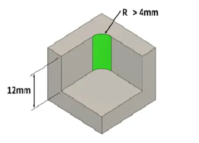
Internal Fillet Radius
An end mill is like a cantilever. Increasing the length or decreasing the diameter of an end mill will significantly increase tool deflection during machining, resulting in chatter and poor surface finish. It is possible to mill fillets with smaller radius, but it will require an end mill with a smaller and slower speeds and feeds. This will increase machining time and cost. Try to use a fillet radius at least 4 times larger than the pocket depth.
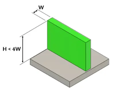
Workpiece Rigidity
If a part is designed with very thin walls, those walls may not be strong enough to endure the cutting forces during CNC machining. They can bend, vibrate, or even break while the tool is cutting. These vibrations - called chatter - create an unstable cutting condition that leads to poor surface finish and makes it difficult or impossible for the machinist to achieve the required tolerances. Whenever possible, keep the height of a machining features to less than 4 times the width.
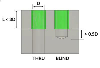
Tapped Holes
A through hole isgenerally easier, safer, and more reliable to tap compared to a blind hole. The tap can pass completely through, so chips have an easy path to escape.There’sless risk of chips packing at the bottom, which can cause tap breakage. In strong materials like steel, it is usually adequate to tap a hole to a depth of 2 times the diameter. For softer materials likealuminum, a depth of 3 times the diameter is adequate. Do not tap a hole beyond the necessary depth, as it does not increase strength beyond this point and it will make it difficult to manufacture.
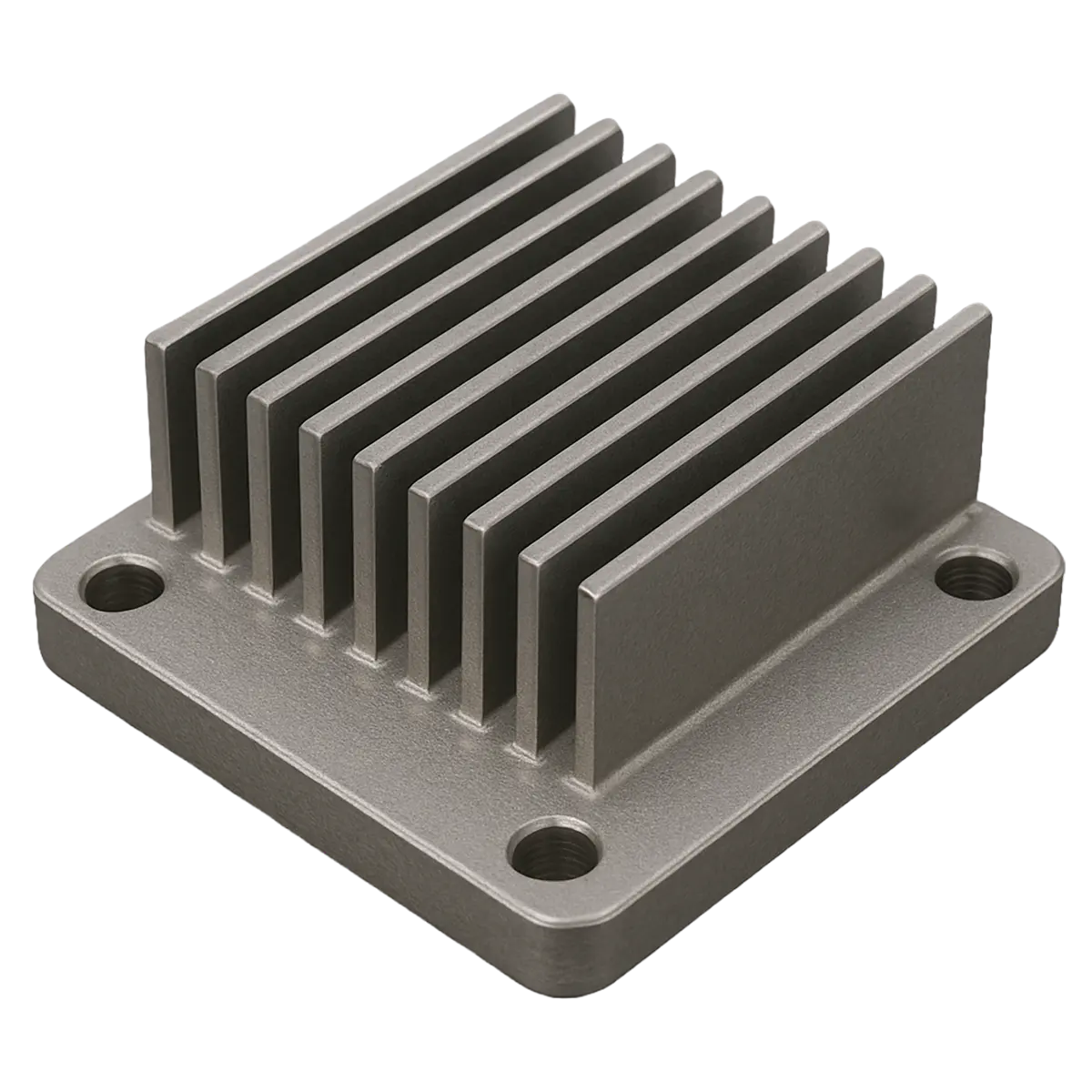
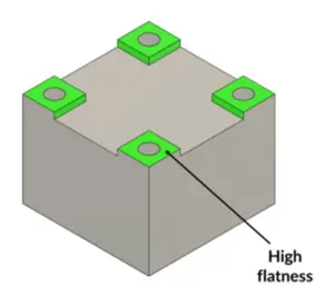
Simplify Flatness Requirements with Small Raised Bosses
Smaller areas are much easier to machine flat, meaning the manufacturer can meet tight tolerances without excessive machining time. Using small bosses with reduced area is a smart, cost-effective way to achieve tight flatness tolerances only where needed, if the boss size and geometry support the functional loads.
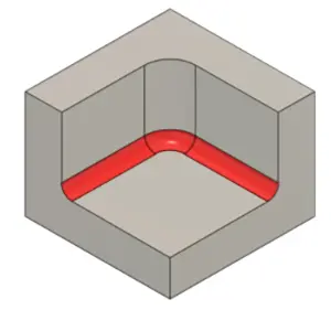
Avoid Floor Fillets
Floor fillets may look nice in CAD, but they often add unnecessary machining difficulty, time, and cost. They should only be used when the design truly requires them. Fillets along the floor of a pocket in CNC milling because they force the machinist to use smaller, weaker tools, which increases cost and decreases accuracy. A floor fillet means the internal corner transitions from the wall to the floor with a radius.
To machine that radius, the cutter must have a smaller tool radius, which means reduced tool rigidity, slower cutting speeds, higher chance of tool deflection or breakage and longer machining times.
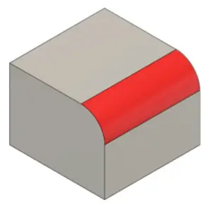
Avoid Top Edge Fillets
For most parts, the purpose of edge relief is simply to remove sharp corners - and a chamfer does this perfectly without added complexity of a fillet. Unless the fillet is functionally required, a chamfer is the machinist-friendly choice. Top-edge fillets need a tool with a specific radius, is more fragile and has limited cutting speeds. This will increase cycle time and force additional tool changes.
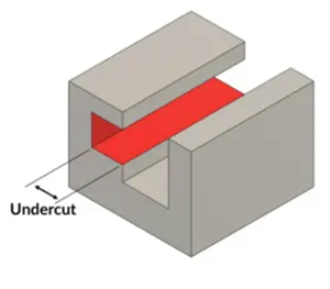
Avoid Undercuts When Possible
Undercuts are not inherently bad, but they should be used only when the part’s function truly requires them, because they add complexity, cost, and tooling constraints in CNC machining.
Undercuts are often avoided because -
- Special tools are needed, such as T-slot cutters or lollipop/end mills, which may not be standard in every shop.
- These tools are fragile and must cut more slowly, increasing machining time.
- Undercuts limit the tool’s access, making chip evacuation and surface finish harder to control.
Sometimes a part needs a retention feature, slot, or locking geometry that cannot be formed any other way. There may be cases where a part needs to match an existing assembly or when the design requires a hidden groove or inverted step. In cases where an undercut feature is unavoidable, keep the undercut as simple, shallow, and accessible as possible so it can be machined with standard undercut tools.
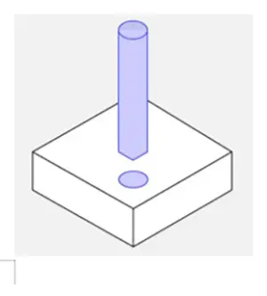
Hole Size and Depth
The diameter of a hole plays a key role in how easily a part can be machined. When creating holes in your design, it’s essential to think about how the hole’s depth relates to its diameter. A common rule of thumb is to keep hole depth to roughly three to five times the hole diameter. Staying within this range makes chip removal easier, minimizes tool wear, and helps ensure the hole is machined accurately. A practical minimum hole diameter is usually in the range of 2 mm to 3 mm. Holes smaller than this can be difficult to produce with precision and often require specialized micro-drills, which add to machining time and overall manufacturing cost.
Surface Finish
Certain surfaces need smoother finishes for sealing, sliding, or optical functions. Finer finishes (lower Ra values) require additional machining steps like slower passes, smaller cutter step-overs, or secondary operations such as polishing or grinding. Aluminum naturally machines to a smoother finish than stainless steel or titanium. Designers should know realistic finish expectations for their material. Some surface finishes, such as anodizing, can slightly affect part dimensions. Using the right finish in the right place ensures optimal performance without unnecessary expense.
Have a part that needs to be CNC machined? Upload your CAD model for a quick no-obligation quote! |