


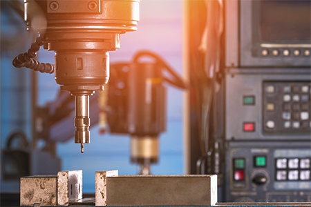
CNC precision machining is CNC machining held to tolerances tighter than the general tolerance classes and verified by dimensional inspection rather than assumed. In practice that means a tolerance of about ±0.025mm (±0.001in) or tighter on the features that matter, on a machine and setup chosen to hold it, with measurement data to prove it.
That definition matters because "precision" is used loosely across the industry. A shop that machines to ISO 2768-m general tolerances and calls the result precision work is describing a ±0.3mm (±0.012in) part on a 20mm feature. That is a normal machined part, not a precision one. The number on the drawing is the only thing that settles the question.
This guide covers what tolerance band each process realistically holds, how surface finish interacts with tolerance, what tighter numbers cost, and how precision is verified once the part is cut.
What Counts as Precision in CNC Machining
There is no legal or standards-body definition of "precision machining." There are, however, well-defined tolerance classes, and those give you a usable dividing line.
General tolerance classes under ISO 2768-1
When a drawing has no individual tolerance on a dimension, ISO 2768-1 fills the gap. The class is called out near the title block as ISO 2768-f, -m, -c, or -v.
| Nominal Size Range | Fine (f) | Medium (m) | Coarse (c) | Very Coarse (v) |
|---|---|---|---|---|
| 0.5 to 3 mm | ±0.05 mm | ±0.1 mm | ±0.2 mm | ±0.5 mm |
| Over 3 to 6 mm | ±0.05 mm | ±0.1 mm | ±0.3 mm | ±0.5 mm |
| Over 6 to 30 mm | ±0.1 mm | ±0.2 mm | ±0.5 mm | ±1.0 mm |
| Over 30 to 120 mm | ±0.15 mm | ±0.3 mm | ±0.8 mm | ±1.5 mm |
| Over 120 to 400 mm | ±0.2 mm | ±0.5 mm | ±1.2 mm | ±2.5 mm |
ISO 2768-f, the tightest general class, allows ±0.1mm (±0.004in) on a 20mm feature. Precision work starts where that class stops being sufficient and a specific tolerance gets written on the dimension instead.
The three bands worth knowing
Most parts fall into one of three practical bands, and knowing which one you are in tells you most of what you need to know about cost, process choice, and inspection.
- General, roughly ±0.1mm to ±0.25mm (±0.004in to ±0.010in). Brackets, enclosures, mounting plates, non-mating structural parts. Held by standard 3-axis milling with no special handling.
- Precision, roughly ±0.025mm to ±0.05mm (±0.001in to ±0.002in). Bearing seats, sealing faces, mating features, shaft diameters. Requires controlled setups, tool wear compensation, and dimensional inspection on the toleranced features.
- High precision, roughly ±0.005mm to ±0.013mm (±0.0002in to ±0.0005in). Reamed and honed bores, ground journals, optical and fluidic sealing surfaces. Usually requires a secondary operation such as grinding, EDM, or lapping, plus temperature-controlled inspection.
Precision machining vs. standard CNC machining
The machines overlap heavily. What separates the two is everything around the cut:
- Tolerance called out per feature rather than a blanket general class
- Process selection driven by the tolerance, including secondary operations where the primary process cannot reach the number
- Thermal and fixturing control, because a 100mm aluminum part grows roughly 0.023mm across a 10°C shop temperature swing, which is most of a ±0.013mm budget
- Measurement that matches the tolerance, meaning a CMM or air gauge rather than calipers once you are under ±0.05mm
Which Process Holds Which Tolerance
Process selection follows the tightest tolerance on the part, not the part's overall shape. This is the table most "what is precision machining" articles leave out, and it is the one that actually changes a design decision.
| Process | Standard Tolerance | Achievable Tolerance | Typical As-Machined Ra |
|---|---|---|---|
| CNC Milling (3, 4, and 5-Axis) | ±0.125 mm (±0.005 in) | ±0.005 mm (±0.0002 in) | 1.6 to 6.3 µm |
| CNC Turning | ±0.075 mm (±0.003 in) | ±0.015 mm (±0.0006 in) | 0.8 to 6.3 µm |
| Wire EDM | ±0.020 mm (±0.0008 in) | ±0.004 mm (±0.00016 in) | 0.3 to 3.2 µm |
| Sinker EDM | ±0.030 mm (±0.0012 in) | ±0.010 mm (±0.0004 in) | 0.3 to 3.2 µm |
Achievable figures apply to specific critical features under controlled conditions, not to every dimension on a part. Specifying the achievable column across an entire drawing is the single most common way to make a part expensive without making it better.
CNC milling
Prismatic parts, pockets, faces, bores, and contoured surfaces. Five-axis milling earns its cost on precision work not through raw accuracy but through setup reduction: every additional setup stacks its own fixturing error onto the tolerance chain, so machining five faces in one setup often holds a tighter true position than three setups on a more accurate 3-axis machine.
CNC turning
Anything axially symmetric. Turning holds diameters more easily than milling holds equivalent widths, because the tool is cutting a single continuous revolved surface. Concentricity between features turned in one chucking is inherently good; concentricity across a re-chuck is not, which is why second-op features get toleranced more loosely unless the part is turned complete on a mill-turn machine.
Wire and sinker EDM
Electrical discharge machining removes material with controlled sparks, so there is no cutting force and no tool pressure deflecting a thin wall. That makes it the default for hardened tool steel, sharp internal corners a cutter cannot reach, thin ribs, and small features in materials that would work-harden under a mill. It is slow and priced accordingly, so it is used for the two or three features that need it, not the whole part.
Secondary finishing operations
When a feature needs to go below what milling or turning holds, it moves to a finishing operation. These are process-general capabilities across the industry:
- Cylindrical and surface grinding: ±0.005mm (±0.0002in) range, Ra 0.2 to 1.6 µm
- Honing: used for bore geometry and finish, sub-micron roundness achievable
- Lapping: Ra 0.01 to 0.2 µm, used for sealing and optical-grade flatness
- Reaming: a practical route to ±0.013mm (±0.0005in) on holes without moving to grinding
Swiss-type turning is the standard route for small-diameter shafts and pins under about 32mm, holding a few microns on diameter through guide-bushing support. Swiss-type capability is [available on request] for parts in that envelope.
Surface Finish Is a Separate Spec from Tolerance
A part can hold ±0.013mm and still have a finish that leaks past a seal. Tolerance controls size and position. Roughness controls the texture of the surface itself, and the two are specified independently.
| Ra (µm) | Ra (µin) | ISO N-Grade | Typical Use |
|---|---|---|---|
| 6.3 | 250 | N9 | Non-critical machined surfaces |
| 3.2 | 125 | N8 | Standard as-machined default |
| 1.6 | 63 | N7 | Mating and bearing surfaces |
| 0.8 | 32 | N6 | Static seal faces, press fits |
| 0.4 | 16 | N5 | Dynamic seal faces |
| 0.1 or below | 4 or below | N3 and finer | Optical, high-pressure sealing |
Ra 3.2 µm is what a part arrives at with no finish callout. Anything below Ra 0.8 µm generally means a grinding, honing, or lapping pass has been added, with the cost and lead time that implies. If a surface only needs to look good rather than seal or slide, a cosmetic finish such as bead blasting or anodizing is far cheaper than machining to a fine Ra.
What Tight Tolerances Actually Cost
Cost does not scale linearly as the tolerance number shrinks. It steps, and the steps are where a process change gets forced.
| Tolerance Band | What Changes | Cost Impact |
|---|---|---|
| ±0.25 mm to ±0.1 mm | Nothing. Standard practice. | Baseline |
| ±0.05 mm | Tighter setup control, in-process gauging | Modest increase |
| ±0.025 mm | Reduced feeds, tool wear compensation, CMM inspection | Noticeable increase |
| ±0.013 mm and tighter | Secondary operation added, temperature-controlled inspection, higher scrap rate | Steep increase |
The largest single jump is the one that forces a secondary operation. A bore that can be interpolated on the mill at ±0.025mm becomes a two-machine part at ±0.008mm, and now it carries grinding setup time, an extra handling step, and its own inspection.
Where to spend tolerance and where to save it
Tolerance is a budget. Spend it on the features that carry function:
- Tighten: bearing seats, sealing diameters and faces, press fits, gear mounting bores, datum features that everything else references, mating hole patterns.
- Loosen: clearance holes, overall envelope dimensions, cosmetic surfaces, pocket depths that nothing seats against, wall thicknesses with no fit requirement.
- Reconsider entirely: any dimension you toleranced tightly by copying a template or applying a blanket note to the whole drawing.
A drawing with three tight features and everything else at ISO 2768-m quotes very differently from the same part with ISO 2768-f applied globally, and the two parts function identically.
How Material Choice Affects Achievable Tolerance
The same machine holds different numbers in different materials, mostly because of thermal expansion, work hardening, and how the material behaves once stress is relieved.
| Material Group | Machinability | Behavior Under Tight Tolerance | Common Precision Uses |
|---|---|---|---|
| Aluminum 6061, 7075 | Excellent | High thermal expansion (about 23 µm/m/°C); parts grow measurably as they cut | Housings, optical mounts, aerospace brackets |
| Stainless 303, 304, 316 | Moderate | Work hardens if feeds drop; 316 is the most difficult of the three | Fluid fittings, medical instruments |
| 17-4 PH Stainless | Moderate | Machine before final aging where possible; heat treat moves dimensions | Valve components, surgical tooling |
| Tool Steels (A2, D2, H13) | Poor when hardened | Usually finished by grinding or EDM after hardening | Dies, punches, mold inserts |
| Titanium Ti-6Al-4V | Poor | Low thermal conductivity concentrates heat at the tool; springback affects thin walls | Aerospace structure, implants |
| Nickel Superalloys (Inconel 718) | Very Poor | Rapid tool wear drives dimensional drift within a single run | Turbine and hot-section components |
| PEEK, Delrin/POM, Nylon | Good | Moisture absorption and creep move dimensions after machining; nylon is the worst offender | Insulators, wear parts, medical fixtures |
Two practical consequences. First, on stress-prone materials and thin-walled parts, a stress-relief step between roughing and finishing is often what makes a tolerance achievable at all. Second, plastics that absorb moisture should be toleranced with their in-service environment in mind, since a nylon part measured dry and installed humid is a different size.
How Precision Gets Verified
An uninspected tolerance is a claim, not a result. The measurement method has to be capable relative to the tolerance itself, generally within about 10% of the tolerance band.
Inspection methods by what you are measuring
| Method | Typical Use | Practical Resolution |
|---|---|---|
| Calipers | Envelope and non-critical dimensions | ±0.02 mm (±0.0008 in) |
| Micrometers | Diameters, thicknesses | ±0.002 mm (±0.0001 in) |
| Bore Gauges and Air Gauges | Bore size and roundness | Sub-micron |
| CMM | GD&T callouts, true position, hole patterns, form | Under 0.002 mm depending on machine |
| Optical Comparator and Vision Systems | Small profiles, thin parts, edges | Feature-dependent |
| Surface Profilometer | Ra, Rz verification | Sub-micron |
Once a feature is toleranced tighter than about ±0.05mm, calipers stop being a valid check. This is a common source of disputes between buyer and supplier: the part was measured with the wrong instrument on one side or the other.
Documentation that comes with the part
For precision work, the inspection record is part of the deliverable:
- First article inspection (FAI) with a ballooned drawing and measured values against every toleranced feature.
- Material certifications traceable to the mill heat number
- Certificate of conformance for the order
- Capability data (Cp/Cpk) where a production run needs statistical evidence rather than sample inspection
FAI reports and material certifications are [provided on request at quote time] for precision orders.
Industry Requirements at a Glance
Different sectors converge on different tolerance and documentation expectations, driven more by qualification requirements than by the geometry itself.
| Industry | Typical Critical Tolerance | Common Materials | Documentation Focus |
|---|---|---|---|
| Aerospace | ±0.013 mm to ±0.05 mm | Al 7075, Ti-6Al-4V, Inconel | Full traceability, FAI, source inspection |
| Medical Device | ±0.013 mm to ±0.025 mm | 316L, Ti-6Al-4V, PEEK | Validation, lot traceability, biocompatible material certs |
| Automotive | ±0.025 mm to ±0.1 mm | Al, steel, engineering plastics | PPAP, capability data at volume |
| Electronics and Semiconductor | ±0.013 mm to ±0.05 mm | Al, copper, ceramics | Cleanliness, surface finish, flatness |
| Energy and Industrial | ±0.05 mm to ±0.1 mm | Stainless, tool steel, superalloys | Pressure test records, material certs |
Clarwe holds ISO 9001:2015. AS9100D and ISO 13485:2016 certified partners are available in the network for programs with a hard flow-down requirement; confirm this at quote time so the job is matched accordingly.
A Practical Checklist for Specifying a Precision Part
Run this before the drawing goes out for quote. Most preventable cost sits in these seven lines.
- Set a general tolerance class in the title block, and make it the loosest class the part tolerates. Everything else gets toleranced individually.
- Tolerance only what carries function. If you cannot name what a tight dimension mates with or seals against, loosen it.
- Define datums explicitly. Ambiguous datums are the most common reason a part measures differently at two shops.
- Use GD&T where position and form matter, per ASME Y14.5. A ±0.025mm positional tolerance on X and Y is more restrictive and less functional than a Ø0.05mm true position callout.
- Specify surface finish separately and only where it matters. Do not apply a fine Ra globally.
- State the inspection expectation. If you need a CMM report on five features, say which five.
- Note post-machining processes. Anodizing adds thickness, plating adds thickness, heat treatment moves dimensions. Say whether the tolerance applies before or after.
Frequently Asked Questions
What tolerance is considered precision machining?
There is no formal standard, but the working threshold is roughly ±0.025mm (±0.001in) or tighter on the toleranced features. Anything held to ISO 2768 general tolerance classes, which allow ±0.1mm or looser on most feature sizes, is standard machining rather than precision machining.
What is the difference between CNC machining and precision machining?
The machines are often the same. Precision machining differs in process control: tolerances specified per feature rather than by a blanket class, process selection driven by the tightest tolerance on the part, controlled thermal and fixturing conditions, and dimensional inspection with instruments capable relative to the tolerance. Standard CNC machining assumes the general tolerance class is sufficient.
What is the tightest tolerance CNC machining can hold?
Wire EDM reaches roughly ±0.004mm (±0.00016in) on select features, and milling reaches roughly ±0.005mm (±0.0002in) under controlled conditions. Below that, parts move to grinding, honing, or lapping. These figures apply to individual critical features, not to every dimension on a part, and they require temperature-controlled inspection to verify meaningfully.
How much does a tighter tolerance increase machining cost?
Cost steps rather than scaling smoothly. Going from ±0.25mm to ±0.1mm typically changes nothing. Going from ±0.05mm to ±0.025mm adds slower feeds, tool wear compensation, and CMM inspection. The largest jump comes when the tolerance forces a secondary operation such as grinding or EDM, which adds a separate setup, extra handling, and a higher scrap rate.
Do I need GD&T, or is ISO 2768 enough?
ISO 2768 handles size only, and only for dimensions with no individual tolerance. If the part has mating features whose position, orientation, or form matters, such as a hole pattern that has to line up with a mating flange, GD&T per ASME Y14.5 is what communicates that. A plus-minus tolerance on a hole location defines a square tolerance zone, while a true position callout defines a round one, which is both more functional and about 57% larger in usable area for the same nominal number.
Can precision machining be done on plastics?
Yes, with two caveats. Engineering plastics such as PEEK, Delrin/POM, and polycarbonate machine to tight tolerances, but they have much higher thermal expansion than metals and several absorb moisture, which moves dimensions after the part leaves the machine. Tolerances tighter than about ±0.05mm on plastics should be specified alongside the measurement conditions and the part's service environment.