


How CNC Milling Machines Are Classified
Machine types are commonly presented as a single list, which causes real confusion when specifying a job. There are three independent classifications, and every machine has one answer for each:
- Spindle orientation: vertical or horizontal
- Axis count: 3, 4, or 5
- Frame configuration: bed, knee, turret, or gantry
A 5-axis vertical bed-type machining center is all three at once. "Vertical" and "bed-type" are not alternatives to each other, and neither is an alternative to "5-axis." Getting this straight matters because the three classifications control different things about your part: orientation controls chip evacuation and part access, axis count controls setup count, and frame configuration controls size and rigidity.
How a CNC Milling Machine Works
From CAD Model to Toolpath
The part starts as a 3D CAD model. CAM software takes that model, plus the stock size, the material, and the available tooling, and generates toolpaths: the actual routes the cutter travels, with feeds, speeds, stepover, and depth of cut assigned to each. A post-processor converts those toolpaths into G-code specific to the machine and control being used. G-code from one machine will not generally run correctly on another without post-processing.
Fixturing and Datum Setup
The workpiece is clamped in a vise, on a fixture plate, or in soft jaws, and the machine is told where it sits. The operator or a spindle-mounted probe establishes the work coordinate system by touching off reference surfaces. This step defines every dimension the machine will cut. If the datum is off by 0.05mm (0.002in), every feature referenced to it is off by 0.05mm.
The Cutting Cycle
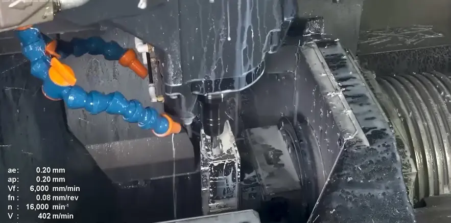
Roughing passes remove bulk material at high feed rates and heavy depth of cut, leaving stock for finishing. Finishing passes take light cuts at higher spindle speeds to hit final dimension and surface finish. Coolant carries heat away from the cutting zone and flushes chips clear. On a job with multiple operations, the automatic tool changer swaps cutters without stopping the cycle.
Inspection
Dimensions get verified against the drawing, typically on a CMM for anything with tight true position or GD&T callouts. On production runs, a first article inspection validates the setup before the rest of the batch runs, and in-process checks catch tool wear before it walks a dimension out of tolerance. Clarwe centralizes final inspection through in-house metrology, which you can read more about on the QA and QC page.
Types of CNC Milling Machines
Vertical Machining Centers (VMC)
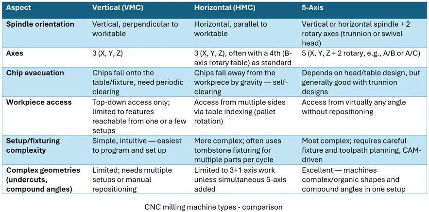
The spindle is oriented vertically, cutting down into a part clamped on the table. VMCs are the most common configuration in job shops because setup is fast, the operator can see the cut, and workholding is straightforward. They are the default for prototypes, low volumes, and any part where most features are accessible from the top.
The main weakness is chip evacuation. Chips fall back into the pocket being cut, and on deep pockets or gummy materials that means recutting chips, which shortens tool life and degrades finish.
Horizontal Machining Centers (HMC)
The spindle runs horizontally into a part mounted on a vertical face or a tombstone fixture. Gravity pulls chips straight down and away from the cut, which is why HMCs handle heavy material removal and long unattended runs better than VMCs. A tombstone fixture holds multiple parts on multiple faces, and pallet changers let one part get loaded while another is cut.
HMCs cost more, take longer to set up, and are harder to justify at low volume. They earn their keep on production quantities.
4-Axis Milling Machines
A 4-axis machine adds a rotary axis, usually indexing the part around the X axis. Used in indexed mode, it rotates the part between faces so several sides can be machined without unclamping. Used in continuous mode, the rotary moves during the cut for wrapped features and helical geometry.
The practical value is setup reduction on parts with features on multiple faces around a single axis.
5-Axis Milling Machines
A 5-axis machine adds two rotary axes, letting the cutter approach the part from effectively any angle. Two modes matter and are frequently confused:
- 3+2 positional (indexed): the rotaries position the part or head, lock, and then a conventional 3-axis cut runs at that angle. This covers most 5-axis work and is what lets five faces of a part be machined in one setup.
- 5-axis simultaneous: all five axes move together during cutting, with the tool axis following the surface. Required for impellers, blisks, turbine blades, and true organic contours.
Clarwe's 5-axis simultaneous capability holds true position down to ±0.015mm (±0.0006in) with spindle speeds to 24,000 RPM and surface finishes below 0.8µm Ra (32µin).
Bed, Knee, Turret, and Gantry Configurations
These describe how the machine's structure carries the load, which sets rigidity and working envelope:
- Bed-type: the table moves along a fixed bed while the spindle head moves vertically. Rigid, and the standard for production machining centers.
- Knee-type: the table sits on a vertically adjustable knee. Flexible and common on manual and light CNC machines, less rigid under heavy cuts.
- Turret: the spindle head moves on a fixed ram while the table stays put, offering good multi-tool access on smaller parts.
- Gantry (bridge): the spindle rides an overhead bridge above a large fixed table. Built for large plates, long weldments, and mold bases.
| Configuration | Spindle | Typical Axes | Strongest At | Main Limitation |
|---|---|---|---|---|
| Vertical Machining Center | Vertical | 3 to 5 | Prototypes, top-face features, fast setup | Chip evacuation in deep pockets |
| Horizontal Machining Center | Horizontal | 4 to 5 | Volume runs, heavy removal, unattended cycles | Higher setup cost, harder to justify at low volume |
| 5-Axis (3+2 Positional) | Either | 5 | Five-sided parts in one setup, deep cavities | Programming and fixturing complexity |
| 5-Axis Simultaneous | Either | 5 | Contoured surfaces, impellers, blades | Highest programming and machine cost |
| Bed-Type | Vertical | 3 to 5 | Rigidity under heavy cuts | Larger footprint |
| Gantry / Bridge | Vertical | 3 to 5 | Large plates and long parts | Lower spindle rigidity than bed-type |
Note what this table deliberately does not include: fixed tolerance, envelope, or spindle speed figures per class. Those are properties of individual machine models, not of machine categories, and any chart presenting them as class-level facts is misleading. For Clarwe's actual published capability by tolerance tier, see the CNC milling services page.
Why Axis Count Changes Tolerance and Costs
Axis count is often described as a precision upgrade. It is not. A 5-axis machine does not inherently cut a more accurate hole than a 3-axis machine. What it changes is how many times the part has to be unclamped, and that is what actually drives tolerance and cost.
Every Setup Adds a Tolerance Stack
Each time a part is refixtured, the machine has to re-establish where the part is. The positional error between a feature cut in setup one and a feature cut in setup two is the accumulated total of fixture repeatability, datum probing or indicating error, and any deflection or shift under clamping load. None of those errors exist between two features cut in the same setup, because the part never moved.
Each time a part is refixtured, the machine has to re-establish where the part is. The positional error between a feature cut in setup one and a feature cut in setup two is the accumulated total of fixture repeatability, datum probing or indicating error, and any deflection or shift under clamping load. None of those errors exist between two features cut in the same setup, because the part never moved.
Marking which dimensions are critical, and which are related to which, tells the manufacturing engineer how to set the part up. A drawing that tolerances everything tightly communicates nothing and forces the most expensive assumption.
When 5-Axis Costs Less Than 3-Axis
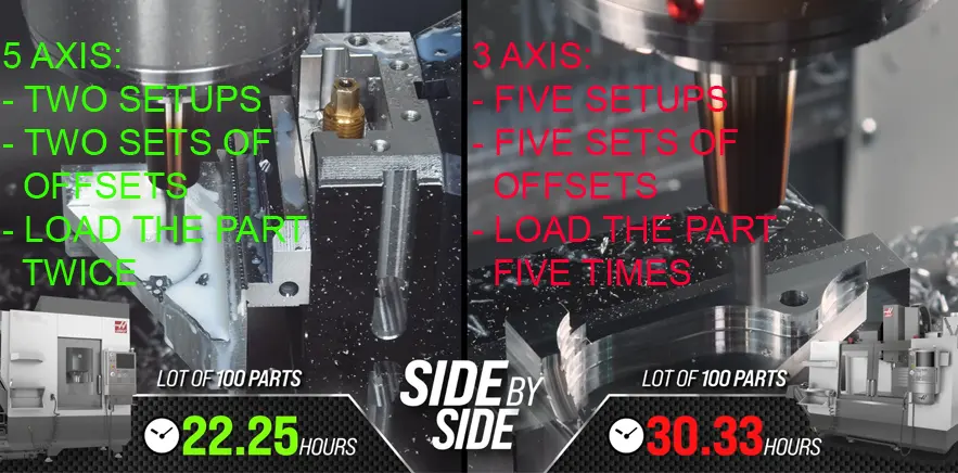
Because setups carry fixed cost, higher axis count often reduces total price rather than raising it. A part needing four separate 3-axis setups requires four fixtures, four programs, four datum establishments, and four rounds of operator handling. The same part in one 3+2 setup on a 5-axis machine needs one of each. The hourly rate is higher, the total is frequently lower, and the tolerance stack disappears.
Tilting the tool also shortens the required tool stickout when reaching into deep cavities. Shorter tools deflect less and chatter less, which improves both dimensional accuracy and surface finish on features a 3-axis machine could only reach with a long, whippy cutter.
CNC Milling Machine Components and What Each One Controls
Spindle
The spindle holds and rotates the cutting tool. Its two governing specs pull against each other: maximum RPM and available torque. High RPM suits aluminum and plastics, where material removal comes from speed. Torque at low RPM suits titanium, Inconel, and tool steels, where cutting speeds have to stay low to control heat. A spindle optimized for one is compromised for the other, which is why shops running mixed materials keep both.
Spindle taper (BT, CAT, HSK) sets which tool holders fit and how much runout the interface contributes. Runout at the spindle nose transfers directly into hole diameter and tool life.
Frame, Column, and Base
The structure carries all cutting load. Cast iron and polymer concrete are used because both damp vibration well, and vibration is what shows up as chatter marks on a finished surface. A machine that flexes under cut takes the tool off its commanded position, which means the part is out of tolerance even though the control believes every axis is exactly where it was told to be. Rigidity is the least visible spec on a datasheet and one of the most consequential.
Linear Axes, Ball Screws, and Guideways
Each linear axis is a servo motor driving a ball screw that moves the table or head along guideways. Ball screw pitch accuracy and preload set positioning accuracy; backlash in a worn screw shows up as dimensional error on direction reversal, most visibly at the transition points of a circular interpolation. Linear guideways move with less friction and support higher rapid rates than box ways, while box ways carry heavier cuts with more damping.
Positioning feedback comes either from a rotary encoder on the motor (semi-closed loop, which cannot see screw thermal growth) or from a linear scale on the axis itself (fully closed loop, which can). This is why a machine's accuracy specification is meaningless without knowing which one it uses.
Table and Workholding
The table is a ground surface with T-slots or a fixture grid. What sits on it does more to determine part quality than most people expect. A vise that distorts a thin-walled part under clamping load produces a part that measures correctly while clamped and springs out of tolerance when released. Soft jaws, vacuum fixtures, and custom fixture plates exist to solve this, and thin-walled or delicate geometry should be flagged at quote time so the fixture is designed for it.
| Supporting System | What It Does | Where It Shows Up in Your Part |
|---|---|---|
| Automatic Tool Changer | Swaps tools mid-cycle from a carousel or chain magazine | Enables multi-operation parts in one program; magazine capacity limits tool count per setup |
| Tool Holders | Clamp the cutter into the spindle taper | Holder runout adds directly to hole size error and uneven tool wear |
| CNC Control | Executes G-code, drives servos, manages look-ahead | Look-ahead quality affects surface finish on 3D contours |
| Coolant System | Removes heat, flushes chips, lubricates the cut | Through-spindle coolant is often required for deep holes and titanium |
| Chip Conveyor | Clears chips from the enclosure | Enables long unattended runs on production quantities |
| Touch Probe | Measures part position and features in-machine | Reduces datum error and catches problems before the part leaves the machine |
Machine Capability vs. Achievable Part Tolerance
What a Machine Spec Sheet Actually Tells You
A machine's stated positioning accuracy describes how precisely it can move an unloaded axis to a commanded coordinate under controlled conditions. Your part tolerance is a different number, and it is always looser. Between the two sit tool deflection, thermal growth in the spindle and screws, workholding distortion, tool wear across the run, material springback, and the datum error discussed above.
Treating the spec sheet number as an achievable part tolerance is a reliable way to write a drawing nobody can quote accurately.
Using ISO 2768 for Non-Critical Dimensions
Most dimensions on most parts do not need a specific callout. ISO 2768-1 supplies general tolerances that apply to every untoleranced linear dimension once you reference the class in or near the title block, which lets you reserve explicit callouts for dimensions that actually matter.
| Nominal Size (mm) | Class f (Fine) | Class m (Medium) |
|---|---|---|
| 0.5 to 3 | ±0.05 mm (±0.002 in) | ±0.1 mm (±0.004 in) |
| Over 3 to 6 | ±0.1 mm (±0.004 in) | ±0.2 mm (±0.008 in) |
| Over 6 to 30 | ±0.15 mm (±0.006 in) | ±0.3 mm (±0.012 in) |
| Over 30 to 120 | ±0.2 mm (±0.008 in) | ±0.5 mm (±0.020 in) |
| Over 120 to 400 | ±0.3 mm (±0.012 in) | ±0.8 mm (±0.031 in) |
ISO 2768 also defines classes c (coarse) and v (very coarse), which are rarely appropriate for machined parts. Class m is the common default for milled work; class f suits precision assemblies. The standard's second part, ISO 2768-2, covers general geometric tolerances for flatness, perpendicularity, and symmetry.
What Tighter Tolerances Cost
Tightening a tolerance adds cost through slower finishing passes, more frequent tool changes, additional inspection, and higher scrap risk. Applied only where function requires it, that cost is worth paying. Applied across a whole drawing by default, it is money spent on nothing.
| Tolerance Tier | Linear Accuracy | True Position | Surface Finish | Typical Use |
|---|---|---|---|---|
| Standard | ±0.125 mm (±0.005 in) | Ø0.20 mm (Ø0.008 in) | 3.2 µm Ra (126 µin) | General fabrication, brackets, enclosures |
| Precision | ±0.025 mm (±0.001 in) | Ø0.05 mm (Ø0.002 in) | 1.6 µm Ra (63 µin) | Fitted assemblies, mating components |
| High-Precision | ±0.010 mm (±0.0004 in) | Ø0.02 mm (Ø0.0008 in) | 0.8 µm Ra (32 µin) | Bearing seats, sealing surfaces |
| Ultra-Precision | ±0.005 mm (±0.0002 in) | Ø0.01 mm (Ø0.0004 in) | 0.4 µm Ra (16 µin) | Optical mounts, instrument-grade components |
As-milled surfaces without a secondary finishing operation typically land between 1.6 and 3.2µm Ra (63 and 126µin). Below that requires dedicated finishing passes, and below roughly 0.4µm Ra (16µin) generally requires a post-process such as lapping or polishing. Options are covered on the surface finishes page.
Matching Machine Configuration to Your Part
| Part Characteristic | Configuration That Fits | Reason |
|---|---|---|
| All features on one face, prismatic | 3-Axis VMC | Single setup, lowest total cost |
| Features on 2 to 4 faces around one axis | 4-Axis Indexed | Rotary indexes between faces without refixturing |
| Features on 5 faces, no undercuts | 5-Axis 3+2 Positional | Tool tilts to reach each face in one setup |
| Contoured surfaces, impellers, blades | 5-Axis Simultaneous | Tool axis follows the surface during the cut |
| Deep pockets needing long tools | 5-Axis or 3+2 | Tilting shortens stickout, reducing deflection and chatter |
| Large plates or long parts | Bed-Type or Gantry | Travel and table capacity govern |
| High volume, multiple faces | HMC with Tombstone Fixturing | Pallet changes and chip clearance support unattended running |
| Prototype quantities, 1 to 10 pieces | 3-Axis VMC | Setup time dominates cost at low volume |
Clarwe's 3-axis capability covers workpieces up to 2,000 × 1,000 × 600mm (78.7 × 39.4 × 23.6in), with 4-axis angular accuracy of ±0.05°. Prototype quantities run on vertical machining centers, and volumes above roughly 100 units move to horizontal machining centers with tombstone fixturing. See rapid prototyping and high-volume production for how the transition is handled.
Materials and How They Affect Machine Selection
Material does more than set the price of stock. It determines which machine characteristics matter.
| Material | Machining Behavior | What the Machine Needs |
|---|---|---|
| Aluminum 6061-T6, 7075-T6 | Free machining, very high removal rates | High spindle RPM matters more than torque |
| Stainless Steel 304, 316 | Work hardens if the tool dwells, chips are stringy | Rigidity, consistent feed, strong coolant delivery |
| Titanium Ti-6Al-4V | Poor thermal conductivity sends heat into the tool | Rigid setup, high-pressure coolant, low surface speed |
| Inconel 718 and Superalloys | Retains strength at temperature, highly abrasive | Maximum rigidity, high torque at low RPM, short tool life budgeted |
| Tool Steels | Hard and abrasive | Rigid machine, planned tool changes mid-run |
| Copper and Brass | Brass cuts freely, copper is gummy and smears | High RPM, sharp uncoated tooling |
| PEEK, Ultem, PTFE, Delrin | Low cutting forces, thermal expansion, burr-prone | High RPM, low clamping force to avoid distortion |
The full stocked list is on the materials page. If a material is not listed, it is usually still sourceable, so ask rather than substituting.
Where CNC Milling Machines Are Used
| Industry | Typical Milled Parts | Common Configuration | Dominant Tolerance Driver |
|---|---|---|---|
| Aerospace | Structural brackets, pocketed ribs, housings, impellers | 5-Axis Simultaneous | True position across faces, thin-wall control |
| Medical Device | Instrument bodies, housings, surgical components | 5-Axis and Precision 3-Axis | Surface finish and material traceability |
| Automotive | Manifolds, transmission components, prototype housings, fixtures | HMC for Volume, VMC for Prototypes | Cycle time and run-to-run repeatability |
| Consumer and Industrial | Enclosures, mounting plates, jigs, tooling | 3-Axis VMC | Cost per part and fit at assembly interfaces |