In CNC machining, every line you draw in CAD dictates the tool a machinist must use and the path that tool must take. Even a seemingly minor feature—like a perfectly sharp internal corner or a deeply threaded hole—can force a manufacturer to use fragile tooling, add manual setups, and slow down their machines.
The easiest way to reduce your CNC machining quotes is to design your part’s geometry around the realities of spinning round cutting tools. Here are the core feature design rules you need to know.
1. Internal Radii: The >1/3 Rule
Because CNC milling tools are cylindrical, it is physically impossible to machine a perfectly sharp inside corner. The tool will always leave a radius equal to its own size.
Many designers simply apply a standard small radius (like 1 mm) to all internal corners. This is a costly mistake. If a pocket is 15 mm deep, a 1 mm radius requires the shop to use a tiny 2 mm end mill. A tool that long and skinny will snap instantly if driven at standard speeds.
The Rule: Design your internal corner radii to be slightly larger than 1/3 of the pocket depth.
- Example: For a 12 mm deep pocket, use a corner radius of at least 4.2 mm. This allows the machinist to use a robust 8 mm end mill to clear out the material quickly.
The "Slightly Larger" Trick: Do not make the corner radius exactly equal to the tool radius. If you want a machinist to use a 10 mm end mill (5 mm radius), design your corner with a 5.2 mm radius. This gives the tool a slightly smooth, circular path into the corner, preventing chatter and leaving a much better surface finish.
Need a sharp corner for a mating square part? Instead of forcing the machinist to use a tiny tool, use a "dog-bone" or "T-bone" corner relief. This involves intentionally over-cutting the corner so the square mating part fits perfectly without needing an expensive, sharp internal corner.
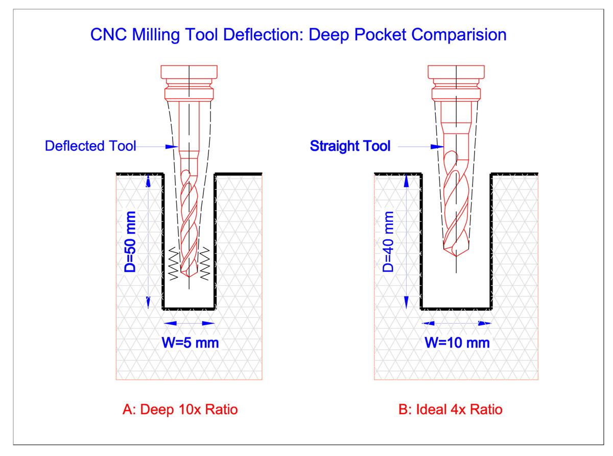
2. Pocket Depth: The 4× Limit
Just because a tool exists doesn't mean you want to pay for the time it takes to use it. When milling deep, narrow cavities, machinists run into a major physics problem: tool deflection.
|
Designing Complex Cavities or Deep Pockets? Rigid automated quoting software often rejects deep pockets or blindly inflates pricing. Our engineering team manually reviews your CAD files to check tool access and deflection risks. Upload your CAD models to get an engineer-led CNC Machining Quote with tailored DFM feedback on your pocket geometries. |
When a long tool is pushed against metal, it bends slightly. This causes "chatter" (vibration), terrible surface finishes, and frequent tool breakage. To compensate, machinists must take incredibly light, slow passes.
The Rule: Keep pocket depths to a maximum of 4× their width.
- Example: If you have a pocket that is 10 mm wide, it should be no deeper than 40 mm.
- If you absolutely must have a deep cavity, consider opening up the width of the pocket or designing the assembly as two separate, shallower parts that bolt together.
3. Holes and Threads: Stop Going Too Deep
Holes and threads are ubiquitous, but they are frequent culprits of inflated quotes if standard sizing is ignored.
Drill Sizes: Always design holes to match standard fractional or metric drill bit sizes. If you design a hole at 6.13 mm, the shop cannot just plunge a standard 6 mm drill bit; they have to slowly interpolate the hole using a smaller end mill, which takes significantly more time.
Thread Depth: The functional strength of a threaded hole is achieved within the first few threads.
The Rule: Never specify a thread depth greater than 3× the hole diameter (and ideally keep it between 1.5× and 2×).
- Tapping a deep hole is risky. As the tap goes deeper, chips accumulate, and the risk of snapping the tap inside your expensive, half-machined part skyrockets. If the tap breaks, the part is often scrapped.
- If you need a through-hole, drill it all the way through, but only tap the depth the fastener actually requires.
4. Setup Reduction: Design for One Plane
Every time an operator has to open the machine doors, unclamp your part, flip it over, re-clamp it, and find the new origin point, you are paying for manual labor. This is called a "setup."
A standard 3-axis CNC mill can only cut from the top down. If your part has holes on the top, a pocket on the bottom, and angled features on the sides, it requires multiple setups.
The Rule: Try to design all complex features (pockets, holes, bosses) on a single face.
- If features must be on multiple faces, try to ensure they are on parallel or perpendicular planes.
- If you include compound angles or undercuts, the part will either require expensive custom fixturing or need to be moved to a 5-axis CNC machine, which carries a higher hourly rate. If your part requires multi-axis machining, you can consult our engineering team to see if the geometry can be simplified to run on a standard 3-axis mill before you finalize your design.
Design for the Process
By sizing your radii to accommodate sturdy end mills, limiting your pocket depths, and using standard threads, you remove the roadblocks that slow down machining. A part designed for standard tools is a part that can be manufactured quickly, consistently, and cheaply.
This article is part of our comprehensive guide to How to Reduce CNC Machining Costs: A Guide to Tolerances, Features, and Design
Frequently Asked Questions
What happens if I design a pocket with a depth exactly at the 4× limit?
While a 4x depth-to-width ratio is generally the safe threshold for standard tooling, it represents the upper boundary for efficient machining. If your design sits exactly at or slightly above this limit, machinists will still need to reduce feed rates and take shallower cuts to mitigate tool deflection. If possible, widening the pocket slightly or introducing a minor draft angle will drastically speed up cycle times and lower production costs.
Why shouldn't I just use standard 1.5× thread depth for all holes?
A thread depth of 1.5x to 2x the hole diameter provides maximum static load holding strength in steel and aluminum applications. Specifying a shallow 1x depth risks stripping threads under high tension, while exceeding $3\times$ depth adds no mechanical holding benefit. It only increases the risk of chip packing and tool breakage during tapping operations.
Can a 3-axis CNC machine cut features on the side of a block?
Yes, but it cannot do it in a single continuous operation. To machine features on a side face, the operator must pause production, manually rotate the physical stock, re-clamp it, and establish a new coordinate origin system. This adds a secondary "setup" charge to your quote. If you want to avoid this labor cost on a standard 3-axis mill, all critical features must face the primary tool spindle on a single plane.