Introduction
Sand casting is ideal for manufacturing large parts that may be difficult or costly to produce using other methods. It works with various metals, including ferrous and non-ferrous alloys, offering great versatility. This process is well suited for low volume production.
Steps involved in Sand Casting Process
Preparation of Pattern
A pattern is a duplicate of the part to be cast and is used to
create the mold cavity. The pattern material is chosen based on the casting volume and process
used.
Common materials for patterns include wood, metal, plastic and wax etc.
The patterns are not made in the exact size or shape of the model, they are adjusted with
allowances to ensure the desired size and shape and to prevent damage to the mold.
Pattern Allowances:
Pattern allowances are the changes made to the pattern to account for various factors. Different types of allowances are applied depending on the factors affecting the pattern.
Shrinkage Allowance:
When molten material cools and
solidifies in the mold, it starts to shrink. To compensate for this, the pattern is made
slightly larger than the final part.

The diagram illustrates that:
In the initial stage, molten liquid is poured into the mold and allowed to solidify. This
process results in the shrinkage of the molten metal, creating gaps at the mold's walls and
reducing the height compared to the initial stage.
Draft Allowance:
Draft allowance, also known as taper
allowance, is essential for removing the pattern from the mold without causing any damage. It is
applied to the vertical surfaces of the pattern, making them slightly tapered compared to the
actual shape of the model.

Machining Allowance:
Machining allowance is the additional
molten material added to the casting, which is later removed during the machining process to
achieve the desired finished shape. Without machining allowance, the machining would directly
occur on the casting, potentially resulting in a product that is undersized.

Distortion Allowance:
Distortion allowance is needed for
casting irregular shapes, such as U-shaped or V-shaped parts, where uneven cooling can cause
internal stresses and distortion. To prevent this, the legs of a U-shaped casting are made
slightly converged, so that when distortion occurs during cooling, the legs become parallel.

Shaking/Rapping Allowance:
When removing the pattern from the
mold, foundry workers often shake it sideways, which can increase the mold cavity size. This
leads to a larger part being produced. To compensate for this, the patterns are made smaller
than the actual desired size.
When a casting needs to be hollow or requires a hole (cavities), a core is placed in the mold.

Core:
Cores are typically made of sand and are dried in ovens before use. They must be strong enough to withstand the molten metal being poured around them and remain intact as the metal solidifies.
Preparation of Mold:
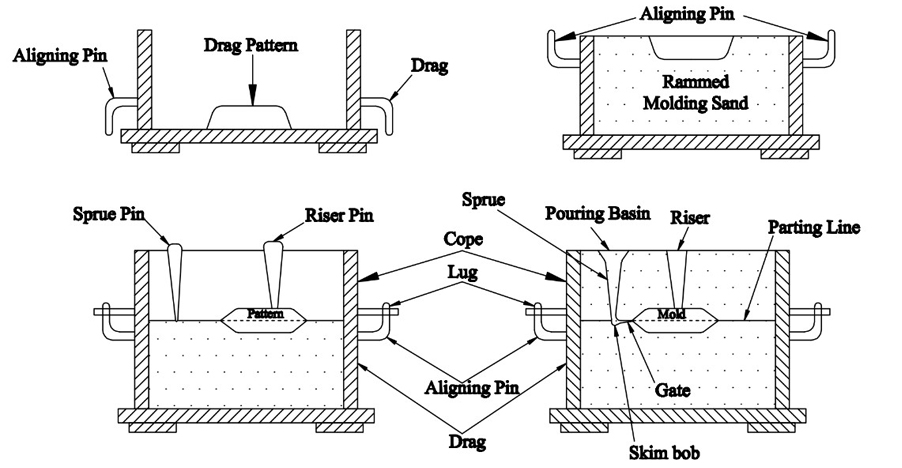
Molding involves placing the pattern, ramming sand around the cavity, adjusting the secondary cavity and then removing the pattern. Once this is done, the cavity is prepared for pouring the molten material. The mold cavity is the primary cavity, while the gating system serves as the secondary cavity in the mold. The mold cavity is a negative imprint of the desired model to be created.Making a mold for a Split Pattern:
1. A suitable size of molding box is selected for the pattern to be placed.2. The bottom part of the pattern is placed on the molding board, in a way that the parting surface faces downwards.
3. Facing sand is sprinkled on the pattern and the molding board, so that it becomes easy to remove the pattern without any molding sand sticking to it.
4. The molding box is placed over the pattern. The box is filled with molding sand and is rammed all over the drag to fill the gaps uniformly in the molding sand.
5. Ramming is done gently and evenly. The excess sand is removed with the help of strike off bar and is leveled until the height of molding box.
6. The molding box forms a lower box called Drag. The drag part is turned over and parting sand is sprinkled around the surface.
7. Next, the top part of the pattern is placed right on the top of the drag part of the pattern.
8. Parting sand is sprinkled across the top part of the pattern. The cope and drag are clamped together temporarily.
9. The other half of the molding box, i.e. cope is placed on the pattern.
10. The pins (sprue & riser pins) are placed vertically and the cope is filled with molding sand which supports the pins to stand at the position.
11. Ramming is performed and the strike off bar is used to level off the cope part.
12. The runner and sprue pins are removed. Using vent wires, vent holes are created to allow the passage of air that is trapped when the molten liquid is poured & while solidifying.
13.Again, parting sand is sprinkled over the top of the cope.
14. Cope and Drag are unclamped & are placed separately in such a way that we can see the parting surfaces of both. Patterns from cope & drag are removed.
15. The mold cavity that is formed is repaired if in case it is disturbed while taking out the patterns & also the other cavities or edges is repaired with help of a stream of air blown onto the surface.
16. Then gates are cut from the lower area of sprue, runner and mold cavity, to allow the flow of molten material when cast is poured.
17. Cores are set if needed for hollow parts. The mold is closed by placing the cope over the drag & is clamped securely to ensure the molten material is poured exactly in the cavity.

Melting and pouring molten metal into the cavity:
Melting for Casting:
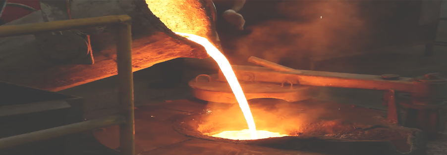
Melting is the process of heating a metal above its melting point to transform it into molten metal. This is done in furnaces and plays a key role in determining the type of casting to be produced.
Pouring for Casting:
Pouring involves transferring the molten metal into the mold cavity through the gating system until the cavity is filled. The metal then solidifies to form the casting.
Gating System:
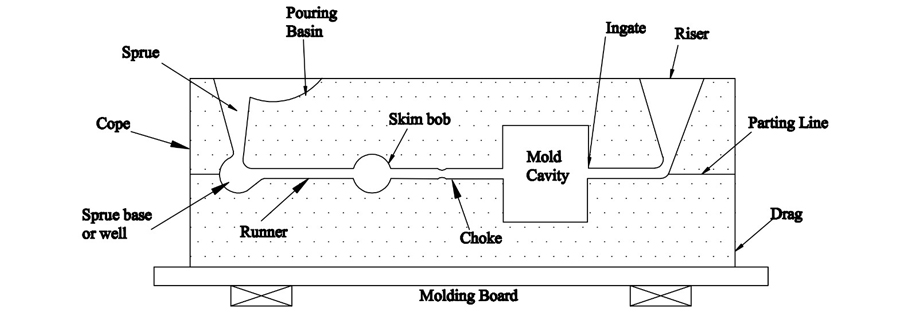
The gating system is the pathway through which molten material flows from the pouring basin, passes through the gate and enters the mold cavity.
Basic Elements of Gating System:
Pouring Basin, Sprue, Sprue Well, Runner, Skim Bob, Gate, Choke, Riser
Pouring Basin:
A hollow, taper-shaped cavity at the top of the mold (cope) where molten metal is poured. It serves as a reservoir to collect slag and prevent it from entering the sprue. The pouring basin ensures controlled flow of molten metal into the sprue.
Sprue:
The sprue is the passage that allows molten metal to flow from the pouring basin into the mold cavity. It controls the flow of molten metal into the cavity.
Sprue Base/Well:
Sprue well is located beneath the sprue; it acts as a reservoir to reduce the momentum of falling molten metal from the sprue. The sprue base helps reduce the velocity of falling molten metal, preventing mold erosion. The molten metal then flows through the runner after changing direction in the sprue well.
Splash Core:
A ceramic piece placed in the sprue well to avoid erosion caused by molten metal splashing at the base of the sprue.
Runner:
A horizontal passage that directs molten metal from the sprue well to the mold cavity.
Skim Bob:
A component that collects impurities flowing through the runner and prevents them from entering the mold cavity.
Gate:
An opening to the mold cavity, which needs to be broken after solidification.
Choke:
A section with a reduced cross-sectional area that traps slag and controls the flow of molten metal, ensuring it doesn't enter the runner.
Riser:
A feature that indicates the fill level of molten metal in the mold. It also compensates for shrinkage during the solidification process.
Solidification:
The molten material poured into the mold cavity cools down over time, solidifying and taking the shape of the mold. This process, where the molten material transitions from liquid to solid, is called solidification.Removal of Unwanted/Excess Material:
Fettling is the process of removing excess material from the casting, such as gates, sprues and risers, as well as checking for any sand residue. It also involves cleaning the final casting and cutting off the risers and runners.After fettling, the casting undergoes an inspection to detect any defects and ensure its quality.
Sand Casting Design Specifications
Engineers designing for sand casting must account for tolerances, surface finish, wall thickness, lead times, and pattern allowances like shrinkage and draft. These specs ensure manufacturability and minimize defects during mold creation, pouring, and finishing.
| Specification | Value/Range | Notes/Details |
|---|---|---|
| Dimensional Tolerance | ±0.030" up to 6"; +0.002"/inch beyond | Per ISO 8062; add draft (1-3°) for pattern removal |
| Surface Finish (RMS) | 250-900 (green sand); 150-600 (resin) | Requires post-machining/polishing for smoother results |
| Min Wall Thickness | 0.15-0.25" | Thinner risks defects; ferrous > non-ferrous |
| Lead Time | 3-5 weeks | 1-3 weeks with 3D printed patterns for prototypes |
| Shrinkage Allowance | 0.8-1.5% | Alloy-dependent (aluminum 1.2%, steel 1.0%); varies by section thickness |
| Draft Angle | 1-3° | External 1-2°; internal 2-3°; reduces friction during withdrawal |
| Machining Allowance | 0.08-0.16" | On critical surfaces; more for rough areas (up to 0.25") |
Advantages of Sand Casting Process
2. The molten metal can fill smaller areas of the cavity, resulting in a cleaner shape.
3. It is cost-effective for large production volumes, requires minimal skilled labor and generates less waste compared to other methods.
Disadvantages of Sand Casting Process
2. The initial cost of creating molds and patterns can be high, particularly for complex shapes or metal parts.
3. Cast parts may have defects like porosity and the production process can be slower compared to other manufacturing techniques.
Applications of Sand Casting Process
Turbine blades, compressor rotors.
Prosthetics, implants, dental crowns.
Electronics Industry:
Heat sinks, connectors, enclosures.Conclusion
At Clarwe, we provide end-to-end casting services with an extensive selection of material options to meet your unique application needs. Our focus is on delivering high-quality, precision-engineered components with rapid turnaround and reliable, on-time delivery.
Backed by ISO-certified processes, seamless coordination and a robust supply network, we proudly serve a range of industries with efficiency and integrity. Whether you're working on a one-off prototype or a full-scale production run, Clarwe ensures precision, performance and consistency—every step of the way.
Need a fast estimate? Get a quote in just a few clicks. Share your project details and we'll provide a timely, accurate pricing solution tailored to your requirements.

