


Introduction
Injection molding is a high-volume manufacturing process ideal for design engineers, product sourcing managers, and OEM manufacturers looking to produce repeatable plastic components at scale. This guide explains how the process works, what materials you can use, common quality challenges, and when injection molding is the right choice for your project.
What is Injection Molding?
Injection molding is a manufacturing process where melted plastic granules are injected under high pressure into a mold cavity, cooled to solidify, and ejected as a finished part. The process repeats automatically, producing thoNorth Americands of identical parts with minimal variation.
Key process parameters
- Injection Pressure: 70-200 MPa (depending on material and part complexity)
- Cycle Time: 10-30 seconds per part (smaller parts); 60+ seconds (larger parts)
- Part Size Range: 50 grams to 25 kg
- Production Volumes: 1,000+ units for economical mold amortization
When to Use Injection Molding
- High production volumes (1,000+ units annually)
- Complex part geometries (ribs, snap fits, thin walls)
- Tight tolerances required (±0.1-0.5 mm typical)
- Multiple colors or finishes without secondary operations
- Cost-sensitive projects where per-unit cost matters more than lead time
When Not to Use Injection Molding
- Low volumes (<500 units) - consider CNC machining or 3D printing instead
- Frequent design changes - mold modification costs add up quickly
- Very large parts (>25 kg) - tooling becomes expensive
- Tight timelines (<4-6 weeks) - mold fabrication takes time
Most Commonly Used Materials in Injection Molding
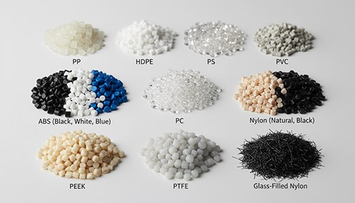
Selecting the right material is critical to part performance, cost, and manufacturability. Below is a guide to the most commonly used materials, organized by performance tier, with typical applications and key properties.
Commodity Plastics (General-Purpose, Cost-Effective)
| Material | Properties | Typical Applications |
|---|---|---|
| Polypropylene (PP) | Lightweight, chemical-resistant, low cost, good fatigue resistance | Packaging, consumer goods, automotive interior trim, hinges |
| High-Density Polyethylene (HDPE) | Rigid, tough, moisture-resistant, food-safe | Containers, storage bins, household appliances, automotive fuel tanks |
| Polystyrene (PS) | Rigid, transparent or opaque options, affordable | Disposable cups, packaging, light covers, protective cases |
| Polyvinyl Chloride (PVC) | Flame-resistant, good electrical insulation, durable | Electrical conduit, flexible tubing, industrial components |
Engineering Plastics (Enhanced Strength & Durability)
These materials offer improved mechanical properties and temperature resistance, suited for functional parts under moderate stress.
| Material | Properties | Typical Applications |
|---|---|---|
| Acrylonitrile Butadiene Styrene (ABS) | Impact-resistant, good rigidity, excellent surface finish, moderate heat resistance | Automotive housings, power tool handles, appliance casings, consumer electronics |
| Polycarbonate (PC) | High impact strength, transparent, heat-resistant to 110°C | Smartphone screens, protective barriers, automotive headlights, safety helmets |
| Nylon (PA6 / PA66) | High tensile strength, low friction, chemical-resistant, good fatigue life | Gears, bearings, bushings, automotive under-hood components, mechanical fasteners |
High-Performance Plastics (Extreme Conditions)
For aerospace, medical, and industrial applications requiring exceptional properties at elevated temperatures or harsh environments.
| Material | Properties | Typical Applications |
|---|---|---|
| Polyetheretherketone (PEEK) | Exceptionally high strength-to-weight, heat-resistant to 260°C, medical-grade, expensive | Aerospace brackets, medical implants, high-temperature seals, offshore components |
| Teflon (PTFE) | Extreme low friction, wide temperature range (-200°C to +260°C), non-stick | Seals, gaskets, valve seats, anti-stick coatings, chemical pipelines |
Injection Molding Machine
Main Components of Injection Molding Machine
Hopper, Barrel, Reciprocating Screw, Heaters, Nozzle, Mold Cavity, Ejector Pins, Crossheads.
The Injection Molding Machine consists of three main functional units
- Injection Unit - includes Hopper, Barrel, Reciprocating Screw, Heaters, Nozzle.
- Mold Unit - includes Mold Cavity, Mold.
- Unit (Hydraulic/Toggle) - includes Ejectors, Crossheads.

1. Injection Unit
The Injection Unit is responsible for melting the granules and injecting them into the mold cavity.
Hopper:A container that holds and dispenses granules into the barrel. It is equipped with a Hopper-Dryer to remove moisture from the granules. Without proper drying, moisture can cause gas formation during melting, delaying the injection process.
Barrel:A chamber surrounded by heaters, where granules from the hopper are melted. The reciprocating screw inside the barrel moves back and forth to help melt and process the granules. The barrel stores the molten material before injection.
Reciprocating Screw:This screw moves granules through the barrel, melting them along the way. It features flights around the shaft that push the granules forward and heat them evenly, ensuring uniform melting. The process of the conversion of raw solid material to liquid form is called “plastification”. The screw operates in three zones: feeding zone, Compression zone (transition) zone, metering zone.
Heaters:Heating bands or coils are clamped around the barrel to maintain a constant temperature for uniform heating of the granules, ensuring consistent product quality.
Nozzle:Once the material is melted, the nozzle injects molten plastic into the mold cavity.
2. Mold Unit
The mold unit is responsible for shaping the product according to the mold cavity and cooling it to solidify. This is done through a process called curing, which involves using cooling systems to control the temperature.
Mold Cavity:The molten material injected through the nozzle fills the mold cavity, where it cools and solidifies. Cooling channels inside the mold use water or air to remove heat and speed up the cooling process.
Ejector Pins:After the molding process, the ejector plates push the finished part out of the mold. The ejector pins extend to remove the part and then retract to close the mold for the next cycle.
3. Clamping Unit
The clamping unit holds the mold in place during the molding process and withstands the pressure and stresses generated. There are two types of clamping systems, depending on the requirements:
Hydraulic Clamping system:Uses cylinders to secure the mold. This system is suitable for machines below the 160-ton range and provides compact mold locking.
Toggle Clamping system:Uses a series of toggle links to open and close the mold. This system ensures the mold remains securely closed during the injection process.
Cross Heads:In the toggle clamping system, the toggle link is connected to the cross-head, which is moved by a driving device, such as a ball spline shaft, to help the crosshead move efficiently.
Working of Injection Molding Machine
Feeding:Polymer granules are fed into the hopper, where they enter the barrel due to gravity.
Heating and Melting:The granules are uniformly heated in the barrel by the reciprocating screw, which melts them into a liquid form.
Injection Chamber:Once fully melted, the molten material collects in the injection chamber of the barrel. As the screw moves backward, the molten material moves forward.
Mold Preparation:Before injection, the clamping unit ensures the mold is securely closed.
Injection:The molten material is injected into the mold cavity through the nozzle. The amount injected, known as "shot size/shot volume," must fill the mold completely, accounting for material shrinkage. The injection speed is also controlled for optimal efficiency and product quality. Shot Size = Mold Cavity (Product Volume + Sprue Volume + Runner Volume) + Shrinkage
Cooling:The mold is cooled through water or air circulation in cooling channels, allowing the material to solidify.
Ejection:Once the part has cooled and solidified, the ejector plates separate and the ejector pins push the finished product out of the mold.
Cycle Repetition:The ejector pins retract, and the mold closes for the next production cycle.
Advantages and Disadvantages of Injection Molding in Manufacturing
Injection molding offers fast, high-volume production with minimal labor and low rejection rates. It can create complex parts with design flexibility, various colors, finishes and allows for the use of multiple materials. The process minimizes waste, ensures precise, high-quality products. It supports recycling of scrap materials and maintains tight tolerances.
Disadvantages:Injection molding has high initial setup and running costs, especially due to automation and expensive machinery. Small-scale production can be costly and design changes require new molds to be created, adding to expenses.
Applications of injection molding
Automotive Components: Bumpers, dashboards, trays, engine parts.
Aerospace Components: Instrument panels, brackets, interiors, housings, fasteners, connectors.
Medical Components: Handles, test tubes, syringes, dental implants.
Consumer Electronics: Remote Controls, keypads, smartphone casings.
Home Appliances: Components for air conditioners, refrigerators, control panels, casings and internal parts
Industrial Components: Gears, bearings, housings, control panels, bushings, etc.
Injection Molding Defects and Preventive Measures

| Defect | What Happens | Root Cause (Mold Design) | Prevention & Solutions | Impact on Cost |
|---|---|---|---|---|
| Jetting | Molten material splatters and solidifies before filling the cavity, leaving visible weld marks | Poor gate design; material enters cavity too fast; sharp gate edges | Optimize gate location and diameter; add restrictors to slow flow; design smooth, rounded gate edges | Mold redesign needed |
| Sink Marks | Indentations appear in thick sections as inner material cools and shrinks faster than outer surface | Insufficient cooling channels in thick areas; uneven cooling distribution | Add cooling channels near thick sections; reduce wall thickness transitions; apply multi-stage cooling strategy | Mold modification required |
| Weld Lines | Visible seams where material fronts meet after diverging around a core or obstacle | Poor mold core placement; inadequate pressure to knit materials together; gate location forces flow split | Reposition gate to avoid core obstacles; increase injection pressure in final stage; optimize core geometry | Mold redesign needed |
| Short Shots (Incomplete Fill) | Part is undersized or missing sections entirely | Gate too small; runners too restrictive; mold cavity not aligned for proper flow | Enlarge gate; optimize runner sizing and placement; ensure mold alignment; improve cooling to allow longer pack time | Mold rework required |
| Flash | Excess material spills over mold edges and solidifies on part surface | Mold wear; parting line misalignment; insufficient clamping surface | Replace or repair parting lines; precision resurface mold; ensure adequate clamping unit tonnage | Mold maintenance or repair |
Injection Molding vs. CNC Machining vs. 3D Printing: Technology Selection Guide
| Factor | Injection Molding | CNC Machining | 3D Printing (FDM / SLA) |
|---|---|---|---|
| Production Volume | 1,000–100,000+ units (high-volume optimized) | 1–500 units (ideal for prototypes & small batches) | 1–100 units (ideal for prototypes & design iterations) |
| Cost Per Unit (at volume) | Lowest at scale: $0.50-$5/unit after mold amortization; low labor cost | Higher per unit: $5-$50+/unit (skill-intensive labor) | Lowest for 1-5 units: $1-$20/unit; cost increases with volume |
| Mold / Tooling Cost | High upfront: $3,000-$50,000+ (depending on complexity) | Low/None: $0-$1,000 (fixturing only) | None: $0 (digital file only) |
| Lead Time to First Part | 4-12 weeks (mold design, fabrication, trial runs) | 1-3 weeks (quick fixturing; depends on complexity) | 1-5 days (fastest for custom parts) |
| Design Changes Cost | Very High: $500-$5,000+ per mold revision; time-consuming | Low: $0-$500; quick parameter adjustment | None: Instant digital modification; reprint immediately |
| Part Complexity | Excellent: Snap fits, undercuts, complex geometries, thin walls | Good but Limited: Deep pockets, fine details possible; some geometries impossible | Good for Geometry, Poor for Strength: Complex shapes; brittle materials |
| Tolerances | Tight: ±0.1-0.5 mm typical; medical/aerospace ±0.05 mm achievable | Very Tight: ±0.05-0.1 mm standard | Loose: ±0.2-0.5 mm typical (not suitable for precision engineering) |
| Surface Finish | Excellent: Mirror-smooth, glossy, embossed textures possible; cosmetic-grade | Good: Clean, functional finish; requires post-processing for cosmetics | Poor: Grainy, rough surface; requires extensive post-processing (sanding, vapor smoothing) |
| Material Options | Wide Range: PP, ABS, PC, Nylon, PEEK, glass-filled composites, elastomers | Limited: Metals (aluminum, steel, titanium), machinable plastics; not ideal for polymers | Very Limited: Resins, FDM plastics; weak compared to injection-molded materials |
| Strength & Durability | High: Isotropic properties; durable for mechanical applications and outdoor use | Very High: Metal parts rated for extreme stress; aerospace-grade | Low: Anisotropic (directional weakness along layer lines); brittle; UV-sensitive |
| Production Speed | Very Fast: 10-60 second cycle times; 100-1,000 parts/day per machine | Slow: 30 min-2 hours per part depending on complexity | Slow: 2-24 hours per part; limited by print speed and material |
| Color/Finish Variety | Unlimited: Multiple colors in single shot; textured surfaces; custom cosmetics | Limited: Single color per run; limited finishes (anodize, paint are secondary ops) | Multi-color Possible: Limited palette; post-painting required for aesthetics |
| Post-Processing Required | Minimal: Deburr, trim gates/runners, test; molded-in finishes reduce secondary work | Moderate: Deburr, clean, anodize/plate/paint for corrosion resistance | Extensive: Sand, cure, paint, assemble; high labor cost adds up |
| Best For |
|
|
|
| Worst For |
|
|
|
Conclusion
Compared to other manufacturing methods such as casting, CNC machining, or 3D printing, injection molding is more cost-effective for large-scale production. Although it requires a high initial investment in molds and machinery, the per-unit cost decreases significantly as production volume increases, making it highly economical for mass manufacturing. While 3D printing can be cost-effective for small production runs, its per-unit cost rises sharply with larger quantities. Therefore, traditional methods like injection molding remain more economical for high-volume manufacturing. Moreover, injection molding contributes positively to the economy by enabling the production of affordable, high-quality goods. It also supports sustainability through the use of recyclable materials, waste reduction, and efficient production processes.
FAQs
What is the injection molding process?
Plastic pellets feed into a hopper, melt in a heated barrel via rotating screw (200-300°C), inject into a clamped mold cavity under 70-200 MPa pressure, cool via channels (10-60s), then eject. Full cycle: 15-60s for small parts.
When is injection molding more cost-effective than CNC machining?
Injection molding excels for high volumes (>10,000 units) with simple-to-moderate geometries, dropping per-unit cost below $0.50 via amortization of mold tooling. CNC suits low-volume prototypes or complex metals better.
What production volumes are ideal for injection molding?
Ideal for medium-to-high volumes: 1,000-1M+ units per run, where mold costs (aluminum/steel) amortize over cycles. Prototypes or <500 units favor 3D printing; ultra-high (>10M) may need multi-cavity molds.
Which materials are commonly used in injection molding?
Thermoplastics like ABS (impact-resistant), PP (flexible/chemical-resistant), PC (transparent/strong), Nylon (wear-resistant), HDPE (durable), PEEK (high-temp/engineering-grade). Selected for strength, flow, and shrinkage (0.5-2%).